Sign In
Upload
Manuals
Brands
Advantech Manuals
Motherboard
PCE-5120
Advantech PCE-5120 Manuals
Manuals and User Guides for Advantech PCE-5120. We have
1
Advantech PCE-5120 manual available for free PDF download: User Manual
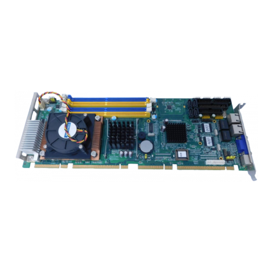
Advantech PCE-5120 User Manual (122 pages)
PICMG 1.3 Full-sized Intel LGA775 processor Card with PCI Express / IPMI / VGA /Dual Gigabit LAN
Brand:
Advantech
| Category:
Motherboard
| Size: 3.43 MB
Table of Contents
User Manual
1
Product Warranty
7
Initial Inspection
8
Table of Contents
9
Chapter 1 Hardware Configuration
18
Introduction
18
Features
19
Specifications
20
System
20
Memory
20
Input/Output
21
Ethernet LAN
21
Industrial Features
21
Mechanical and Environmental Specifications
21
Jumpers and Connectors
22
Table 1.1: Jumpers
22
Table 1.2: Connectors
22
Board Layout: Jumper and Connector Locations
24
Figure 1.1: Jumper and Connector Locations
24
PCE-5120 Block Diagram
25
Figure 1.2: PCE-5120 Block Diagram
25
Safety Precautions
26
Jumper Settings
27
CMOS Clear (CMOS1)
27
How to Set Jumpers
27
Table 1.3: CMOS (CMOS1)
27
(Jsetcom2)
28
COM2 RS 232/422/485 Mode Selector (JSETCOM2)
28
Table 1.4: Watchdog Timer Output (JWDT1)
28
Watchdog Timer Output (JWDT1)
28
System Memory
29
CPU FSB and Memory Speed
29
Memory Installation Procedures
29
Cache Memory
29
Processor Installation
30
CPU Cooler Installation
32
Chapter 2 Connecting Peripherals
34
Introduction
34
IDE Connectors (IDE1)
34
Floppy Drive Connector (FDD1)
35
Parallel Port (LPT1)
36
VGA Connector (VGA1)
37
Serial Ports (COM1, COM2, COM3, COM4)
37
PS/2 Keyboard and Mouse Connector (KBMS1)
38
External Keyboard & Mouse (KBMS2)
38
CPU Fan Connector (CPFAN1)
39
Front Panel Connectors (JFP1, JFP2, JFP3)
39
ATX Soft Power Switch (JFP1 / PWR_SW)
40
Reset (JFP1 / RESET)
40
Hdd Led (Jfp2 / Hddled)
40
SM Bus Connector (JFP2 / SNMP)
40
External Speaker (JFP2 / SPEAKER)
40
Power LED and Keyboard Lock Connector (JFP3 / PWR_LED&KEY LOCK)
40
Table 2.1: ATX Power Supply LED Status (no Support for at Power)
41
H/W Monitor Alarm (JOBS1)
41
Table 2.2: Hardware Monitor Alarm Setting
41
Gigabit LAN RJ45 Connector (LAN1, LAN2)
42
AC'97 Link Connector (AC97)
42
Serial ATA2 Interface
43
LAN1 and LAN2 LED Connector (LANLED1)
43
BMC Connector (BMC1)
44
Usb (Usb12, Usb34)
44
Chapter 3 Award BIOS Setup
46
Introduction
46
CMOS RAM Auto-Backup and Restore
46
Entering Setup
47
Figure 3.1: Award BIOS Setup Initial Screen
47
Standard CMOS Setup
47
Date
47
IDE Channel 0/1 Master/Slave
47
Time
47
Drive a / Drive B
48
Figure 3.2: Standard CMOS Features Screen
48
Halt on
48
Memory
48
Advanced BIOS Features
49
Figure 3.3: Advanced BIOS Features Screen
49
CPU Features
49
Hard Disk Boot Priority
50
Virus Warning
50
CPU L1, L2 & L3 Cache
50
Hyper-Threading Technology
50
Quick Power on Self Test
50
First/Second/Third Boot Device
50
Boot Other Device
50
Swap Floppy Drive
50
Boot up Floppy Seek
50
Boot up Numlock Status
50
Typematic Rate Setting
51
Typematic Rate (Chars/Sec)
51
Typematic Delay (Msec)
51
Security Option
51
APIC Mode
51
Advanced Chipset Features
52
Figure 3.4: Advanced Chipset Features Screen
52
DRAM Timing Selectable
52
CAS Latency Time
52
DRAM RAS# to CAS# Delay
53
DRAM RAS# Precharge
53
Precharge Delay (T RAS)
53
System Memory Frequency
53
System BIOS Cacheable
53
Video BIOS Cacheable
53
Memory Hole at 15M-16M
53
PCI-Express Root Port Func
54
PEG / Onchip VGA Control
54
PEG Force X1
54
On-Chip Video Memory Size
54
On-Chip Frame Buffer Size
54
DVMT Mode
54
DVMT / FIXED Memory Size
54
Init Display First
54
Integrated Peripherals
55
Figure 3.5: Integrated Peripherals
55
Figure 3.6: On-Chip IDE Device
55
IDE HDD Block Mode
55
IDE DMA Transfer Access
55
On-Chip Primary / Secondary IDE Device
56
SATA Mode
56
Note: On-Chip Serial ATA
56
PATA IDE Mode
56
SATA Port
56
Figure 3.7: Onboard Device
57
USB Controller
57
USB 2.0 Controller
57
USB Keyboard / Mouse Support
57
AC97 Audio
57
Onboard LAN1 Control
57
Onboard LAN2 Control
57
Figure 3.8: Super I/O Device
58
Onboard FDC Controller
58
Onboard Serial Port 1
58
Onboard Serial Port 2
58
UART Mode Select
58
Rxd, Txd Active
58
IR Transmission Delay
58
UR2 Duplex Mode
59
Use IR Pins
59
Onboard Parallel Port
59
Parallel Port Mode
59
EPP Mode Select
59
ECP Mode Use DMA
59
Onboard Serial Port 3
59
Onboard Serial Port 4
59
Power Management Setup
60
Figure 3.9: Power Management Setup Screen (1)
60
PCI Express PM Function
60
Power Supply Type
60
ACPI Function
60
Power Management
61
Table 3.1: Power Saving
61
Video off Method
61
Video off in Suspend
61
Suspend Type
61
Modem Use IRQ
61
Suspend Mode
61
HDD Power down
61
Soft-Off by PWR-BTTN
62
Poweron by LAN
62
Poweron by Modem
62
Poweron by Alarm
62
Primary IDE 0 (1) and Secondary IDE 0 (1)
62
Fdd, Com, Lpt Port
62
Pci Pirq [A-D]
62
PWRON after PWR-Fail
62
Pnp/Pci Configurations
63
Figure 3.10:Pnp/Pci Configurations Screen
63
Reset Configuration Data
63
Resources Controlled by
63
PCI / VGA Palette Snoop
63
Maximum Payload Size
63
PC Health Status
64
Figure 3.11:PC Health Status Screen
64
Case Open Warning
64
PCE-5120 User Manual
64
CPU FAN Speed
64
CPU Warning Temperature
64
Current CPU Temperature
64
Current System Temperature
64
System FAN 1 / 2 Speed
64
VCORE and Other Voltages
64
Frequency / Voltage Control
65
Figure 3.12:Spread Spectrum Control Screen
65
CPU Clock Ratio
65
Spread Spectrum
65
Load Setup Defaults
66
Figure 3.13: Load Setup Defaults Screen
66
Save & Exit Setup
66
Exit Without Saving
66
Chapter 4 Chipset Software Install Utility
68
Before You Begin
68
Introduction
68
Windows XP Driver Setup
69
Chapter 5 VGA Setup
74
Introduction
74
Windows XP Driver Setup
74
Chapter 6 Onboard Security Setup
78
Introduction
78
Windows XP Driver Setup
78
Using the OBS Hardware Doctor Utility
81
Introduction
84
Features
84
Installation
84
Chapter 7 LAN Configuration
84
Win XP Driver Setup (Intel 82573)
85
Introduction
90
SATA RAID Driver and Utility Setup
90
Chapter 8 SATA RAID Setup
90
Chapter 9 IPMI
92
IPMI Introduction
92
Definitions
92
Table 9.1: Supported IPMI Commands
92
IPMI Function List
92
IPMI OEM Command Lists
96
Appendix A Watchdog Timer
98
Programming the Watchdog Timer
98
A.1.2 Jumper Selection
98
Jumper Selection
98
Table A.1: Watchdog Timer Registers
100
A.1.4 Example Program
101
Example Program
101
Watchdog Timer Overview
98
Appendix B I/O Pin Assignments
108
Table B.1: IDE Hard Drive Connector (IDE1)
108
IDE Hard Drive Connector (IDE1)
108
Floppy Drive Connector (FDD1)
109
Table B.2: Floppy Drive Connector (FDD1)
109
Parallel Port Connector (LPT1)
110
Table B.3: Parallel Port Connector (LPT1)
110
VGA Connector (VGA1)
111
Table B.4: VGA Connector (VGA1)
111
Serial Port (COM1, COM2, COM3, COM4)
112
PS/2 Keyboard/Mouse Connector (KBMS1)
113
(Kbms1)
113
External Keyboard Connector (KBMS2)
113
B.7 External Keyboard Connector (KBMS2)
113
Table B.7: External Keyboard Connector (KBMS2)
113
CPU Fan Power Connector (CPUFAN1)
114
(Cpufan1)
114
Power LED and Keyboard Lock Connector (JFP3 / PWR_LED & KEY LOCK)
114
(Jfp3 / Pwr_Led & Key Lock)
114
B.9 Power LED and Keyboard Lock Connector (JFP3 PWR_LED & KEY LOCK)
114
External Speaker Connector (JFP2 / SPEAKER)
115
Reset Connector (JFP1 / RESET)
115
Table B.11: Reset Connector (JFP1 / RESET)
115
Hdd Led (Jfp2 / Hddled)
116
Table B.12: HDD LED (JFP2 / HDDLED)
116
ATX Soft Power Switch (JFP1 / PWR_SW)
116
(Jfp1 / Pwr_Sw)
116
AC'97 Link Connector (AC97)
117
Table B.14: AC'97 Link Connector (AC97)
117
SM Bus Connector (JFP2 / SNMP)
117
Table B.15: SM Bus Connector (JFP2 / SNMP)
117
LAN1 and LAN2 LED Connector (LANLED1)
118
(Lanled1)
118
System I/O Ports
119
B.17 System I/O Ports
119
Table B.17: System I/O Ports
119
DMA Channel Assignments
120
Table B.18: DMA Channel Assignments
120
Interrupt Assignments
121
B.19 Interrupt Assignments
121
Table B.19: Interrupt Assignments
121
1St MB Memory Map
121
Table B.20: 1St MB Memory Map
121
PCI Bus Map
122
Table B.21: PCI Bus Map
122
Advertisement
Advertisement
Related Products
Advantech PCE-5127
Advantech PCE-5126
Advantech PCE-5026
Advantech PCE-5128
Advantech PCE-5129
Advantech PCE-5029
Advantech PCE-5131
Advantech PCE-5031
Advantech PCE-3028
Advantech PCE-7131
Advantech Categories
Motherboard
Computer Hardware
Desktop
Touch Panel
PCI Card
More Advantech Manuals
Login
Sign In
OR
Sign in with Facebook
Sign in with Google
Upload manual
Upload from disk
Upload from URL