Sign In
Upload
Manuals
Brands
Advantech Manuals
Computer Hardware
CA-6178VE-00B1
Advantech CA-6178VE-00B1 Manuals
Manuals and User Guides for Advantech CA-6178VE-00B1. We have
1
Advantech CA-6178VE-00B1 manual available for free PDF download: User Manual
Advantech CA-6178VE-00B1 User Manual (137 pages)
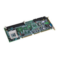
Full-size socket 370 Intel Pentium III processor-based PCI/ISA-bus CPU card
Brand:
Advantech
| Category:
Computer Hardware
| Size: 3.04 MB
Table of Contents
Copyright Notice
2
Technical Support
3
Product Warranty
6
Initial Inspection
7
Table of Contents
8
Chapter 1 Hardware Configuration
16
Introduction
17
Features
18
Specifications
20
System
20
Memory
20
Input/Output
21
VGA Interface
21
SCSI Interface
21
Ethernet LAN (PCA-6178E/6168F Only)
21
Solid State Disk
21
Industrial Features
22
Mechanical and Environmental Specifications
22
Board Layout: Main Features
23
Figure 1-1: Board Layout: Main Features
23
Jumpers and Connectors
24
Table 1-1: Jumpers
24
Table 1-2: Connectors
25
Board Layout: Jumper and Connector Locations
26
Figure 1-2: Board Layout: Jumper and Connecter Locations
26
Safety Precautions
27
Jumper Settings
28
How to Set Jumpers
28
CPU Clock Ratio Setting (SW1)
28
CPU Type Select (SW2)
29
Table 1-3: CPU Clock Ratio Setting (SW1)
29
Table 1-4: CPU Type Select (SW2)
29
CMOS Clear (J1)
30
Watchdog Timer Output (J2)
30
Table 1-5: CMOS Clear (J1)
30
Table 1-6: Watchdog Timer Output (J2)
30
Diskonchip 2000 Flash Disk Address Select (J3)
31
System Memory
33
Sample Calculation: DIMM Memory Capacity
33
Table 1-8: DIMM Module Allocation Table
33
Table 1-9: DIMM Memory Capacity Sample Calculation
33
Supplementary Information about Dimms
34
Memory Installation Procedures
35
Cache Memory
35
Figure 1-3: DIMM Installation
35
CPU Installation
36
Chapter 2 Connecting Peripherals
38
Floppy Drive Connector (CN3)
40
Parallel Port (CN4)
40
SCSI Connector (CN5)
41
USB Port (CN6)
42
VGA Connector (CN7)
42
10/100Base-T Ethernet Connector (CN8)
43
Serial Ports (CN9: COM1; CN10: COM2)
43
Table 2-1: Serial Port Connections (COM1, COM2)
43
PS/2 Keyboard and Mouse Connector (CN11)
44
External Keyboard Connector (CN12)
44
Infrared (IR) Connector (CN13)
45
CPU Fan Connector (CN14)
45
Front Panel Connectors (CN16, CN17, CN18, CN19 and CN21)
46
Keyboard Lock and Power LED (CN16)
46
External Speaker (CN17)
46
Reset (CN18)
46
Table 2-2: PS/2 or ATX Power Supply LED Status
46
Hdd Led (Cn19)
47
ATX Soft Power Switch (CN21)
47
ATX Power Control Connectors (CN20 and CN21)
47
ATX Feature Connector (CN20) and Soft Power Switch Connector (CN21)
47
Controlling the Soft Power Switch
48
Chapter 3 Award BIOS Setup
50
Introduction
51
Entering Setup
51
Standard CMOS Setup
52
CMOS RAM Backup
52
BIOS Features Setup
53
Virus Warning
53
Quick Power on Self Test
54
Boot Sequence
54
Boot up Floppy Seek
55
Boot up Numlock Status
55
Gate A20 Option
55
Typematic Rate Setting
55
Typematic Rate (Chars/Sec)
55
Typematic Delay (Msec)
56
Security Option
56
PCI/VGA Palette Snoop
56
OS Select for DRAM > 64MB
56
Video BIOS Shadow
56
C8000-CBFFF Shadow / DC000-DFFFF Shadow
57
Chipset Features Setup
57
SDRAM RAS to CAS Delay
58
SDRAM RAS Precharge Time
58
SDRAM CAS Latency Time
58
DRAM Data Integrity Mode
58
Bit I/O Recovery Time / 8 Bit I/O Recovery
58
Memory Hole at 15M-16M
58
AGP Aperture Size (MB)
59
Power Management Setup
59
Power Management
59
HDD Power down
59
Soft-Off by PWR-BTTN
60
PCI Configuration Setup
60
IRQ-XX Assigned to : PCI/ISA Pnp
60
DMA-X Assigned to : PCI/ISA Pnp
61
Used MEM Base Addr : N/A
61
Load BIOS Defaults
61
Load Setup Defaults
61
Integrated Peripherals
62
IDE HDD Block Mode
62
IDE Primary Master/Slave PIO/UDMA Mode, IDE Secondary Master/Slave PIO/UDMA Mode (Auto)
62
On-Chip PCI IDE Primary/Secondary
62
Onboard FDC Controller
63
Onboard Serial Port 1 (3F8H/IRQ4)
63
Onboard Serial Port 2 (2F8H/IRQ3)
63
Onboard Parallel Port (378H/IRQ7)
63
Parallel Port Mode (ECP + EPP)
63
ECP Mode Use DMA
63
Password Setting
64
IDE HDD Auto Detection
64
Save & Exit Setup
65
Exit Without Saving
65
Chapter 4 PCI SVGA Setup
66
Before You Begin
67
Features
67
Installation
68
Driver Installation
70
Necessary Prerequisites
70
Before You Begin
70
Changing Display Drivers in Windows
70
Changing Color Schemes
70
Windows 95/98 Drivers Setup Procedure
71
Windows NT Drivers Setup Procedure
73
Chapter 5 LAN Configuration
76
Introduction
77
Features
77
Driver Installation
78
Windows 95/98/98SE Drivers Setup Procedure
79
Windows NT Drivers Setup Procedure
86
Windows NT Wake-On-LAN Setup Procedure
91
Chapter 6 SCSI Setup and Configurations
94
Introduction
95
Before You Begin
95
Basic Rules for SCSI Host Adapter and Device
96
Installation
96
Configuring the SCSI Adapter
96
SCSI Terminators
97
SDMS Drivers
98
Chapter 7 Onboard Security Setup
100
Introduction
101
Driver Installation
101
Before You Begin
101
Windows 95 Drivers Setup Procedure
102
Figure 7-2: Setup under Win95
105
Figure 7-3: Restarting Windows
105
Windows NT Driver Setup Procedure
111
Programming the Watchdog Timer
116
Appendix A Programming the Watchdog Timer
117
Appendix A Programming the Watchdog Timer
118
Appendix B Pin Assignments
120
IDE Hard Drive Connector (CN1, CN2)
121
Table B-1: IDE Hard Drive Connector (CN1, CN2)
121
Floppy Drive Connector (CN3)
122
Table B-2: Floppy Drive Connector (CN3)
122
Parallel Port Connector (CN4)
123
Table B-3: Parallel Port Connector (CN4)
123
SCSI Connector (CN5)
124
Table B-4: SCSI Connector (CN5)
124
USB Connector (CN6)
125
Table B-5: USB1/USB2 Connector (CN6)
125
Table B-6: VGA Connector (CN7)
125
VGA Connector (CN7)
125
Ethernet 10/100Base-T RJ-45 Connector (CN8)
126
COM1/COM2 RS-232 Serial Port (CN9, CN10)
126
Table B-7: Ethernet 10/100Base-T RJ-45 Connector (CN8)
126
Table B-8: COM1/COM2 RS-232 Serial Port (CN9, CN10)
126
Keyboard and Mouse Connnector (CN11)
127
B.10 External Keyboard Connector (Cn)
127
External Keyboard Connector (CN12)
127
Table B-10: External Keyboard Connector (CN12)
127
Table B-9: Keyboard and Mouse Connector (CN11)
127
B.12 Cpu Fan Power Connector (Cn)
128
IR Connector (CN13)
128
CPU Fan Power Connector (CN14)
128
Table B-11: IR Connector (CN13)
128
Table B-12: CPU Fan Power Connector (CN14)
128
B.14 External Speaker Connector (Cn)
129
Power LED and Keylock Connector (CN16)
129
External Speaker Connector (CN17)
129
Table B-13: Power LED and Keylock Connector (CN16)
129
Table B-14: External Speaker (CN17)
129
ATX Feature Connector (CN20)
130
B.16 Hdd Led Connector (Cn)
130
B.17 Atx Feature Connector (Cn)
130
Reset Connector (CN18)
130
HDD LED Connector (CN19)
130
Table B-15: Reset Connector (CN18)
130
Table B-16: HDD LED Connector (CN19)
130
Table B-17: ATX Feature Connector (CN20)
130
System I/O Ports
131
Table B-18: System I/O Ports
131
DMA Channel Assignments
132
Interrupt Assignments
132
Table B-19: DMA Channel Assignments
132
Table B-20: Interrupt Assignments
132
1St MB Memory Map
133
PCI Bus Map
133
Table B-21: 1St MB Memory Map
133
Table B-22: PCI Bus Map
133
Appendix C Diskonchip® 2000 Installation Guide
134
Diskonchip 2000 Quick Installation Guide
135
Diskonchip® 2000 Installation Instructions
135
Addtional Information and Assistance
136
Advertisement
Advertisement
Related Products
Advantech CA-6178V-00B1
Advantech CA-6178VS-00B1
Advantech CA-6178F-00B1
Advantech CPC-2520
Advantech ADAM CPU 82 Series
Advantech ADAM CPU 821 DPM Series
Advantech ADAM CPU 821 NET Series
Advantech ADAM CPU 8214
Advantech ADAM CPU 8215
Advantech ADAM CPU 8216
Advantech Categories
Motherboard
Computer Hardware
Desktop
Touch Panel
Network Router
More Advantech Manuals
Login
Sign In
OR
Sign in with Facebook
Sign in with Google
Upload manual
Upload from disk
Upload from URL