Sign In
Upload
Manuals
Brands
Advantech Manuals
Motherboard
AIMB-503
Advantech AIMB-503 Manuals
Manuals and User Guides for Advantech AIMB-503. We have
1
Advantech AIMB-503 manual available for free PDF download: User Manual
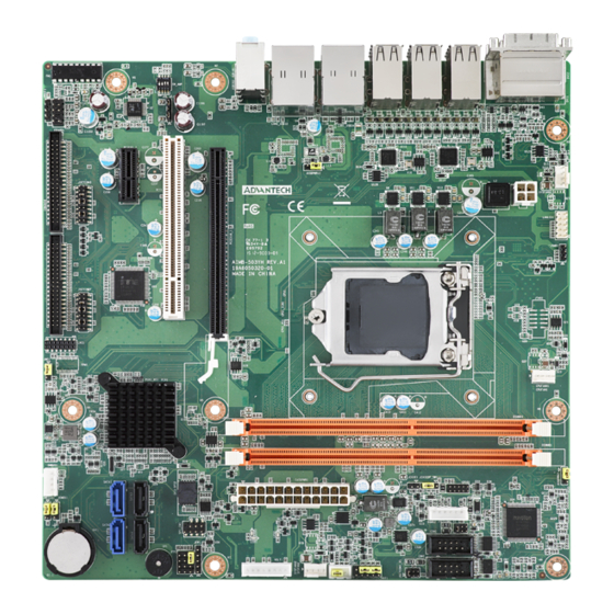
Advantech AIMB-503 User Manual (110 pages)
Intel Core i7/i5/i3 LGA1150 MicroATX with CRT/DP/DVI/ LVDS, 10 COM, 4 USB 3.0, 7 USB 2.0, Dual LAN
Brand:
Advantech
| Category:
Motherboard
| Size: 7.44 MB
Table of Contents
Declaration of Conformity
4
Ordering Information
5
Table of Contents
7
Chapter 1 General Information
11
Introduction
12
Features
12
Specifications
12
System
12
Memory
12
Input/Output
13
Graphics
13
Ethernet LAN
13
Industrial Features
13
Mechanical and Environmental Specifications
13
Jumpers and Connectors
14
Board Layout: Jumper and Connector Locations
15
AIMB-503 Board Diagram
16
Safety Precautions
17
Jumper Settings
18
CMOS Clear (CMOS1)
18
How to Set Jumpers
18
JLVDS1: LCD Power 3.3 V/5 V/ 12 V Selector
18
PSON1: ATX, at Mode Selector
19
Table 1.5: JLVDS1: LCD Power 3.3 V/5 V/ 12 V Selector
19
(Jsetcom3 & Jsetcom7)
20
COM3/COM7 RS232/422/485 Mode Selector (JSETCOM3 & JSETCOM7)
20
JIR1+JWDT1+JOBS1: CIR Interface, Watchdog Timer Output and OBS Beep
20
Com1 & Com2
21
JCASE1: Case Open Sensor
21
JSETCOM1_V1, JSETCOM2_V1: Power Setting for COM1 & COM2
21
System Memory
21
Memory Installation Procedures
21
Processor Installation
21
Chapter 2 Connecting Peripherals
23
Introduction
24
USB Ports (LAN1_USB45/LAN2_USB12/USB3/USB67/USB89/USB1011)
24
USB Power Switch
25
VGA1/ DVI-D DP1 Connector
26
Serial Ports (COM1~COM10)
27
PS/2 Keyboard and Mouse Connector (Kbms1)/External PS/2 Keyboard and Mouse Connector (KBMS2)
28
CPU Fan Connector (CPU_FAN1)
28
System FAN Connector (SYSFAN1/2)
29
Power Switch/Hdd Led/Smbus/Speaker, Power LED and Keyboard Lock Pin Header (JFP1,JFP2)
29
Line Out, MIC in Connector (AUDIO1)
30
SMBUS Header (SMBUS1)
31
Serial ATA Interface (SATA1 ~ SATA3)
31
Adjust Audio Volume Connector (AMP1)
32
PCI Express X16 Slot
33
Front Headphone Connector (FPAUD1)
34
ATX Power Connector (EATXPWR1, ATX12V1)
35
SPI Flash Connector(SPI_CN1)
36
LCD Inverter Connector (INV1)
37
LVDS Connector (LVDS1)
37
General Purpose I/O Connector (GPIO1)
38
LPC Connector for Debug (LPC1)
39
BIOS Operation
41
Chapter 3 BIOS Operation
41
Introduction
42
BIOS Setup
42
Main BIOS Setup
43
Advanced BIOS Features
44
PCI Configuration
45
PCI Express Settings
46
ACPI Settings
47
Trusted Computing
48
S5 RTC Wake Settings
48
CPU Configuration
49
SATA Configuration
49
Intel Rapid Start Technology
50
USB Configuration
50
Super IO Configuration
51
Smart Fan Configuration
61
Chipset Configuration Setting
62
PCH-IO Configuration
62
USB Configuration
67
PCH Azalia Configuration
68
System Agent Configuration
68
NB Pcie Configuration
71
Memory Information
72
Boot Configuration
72
Security Setting
73
Save & Exit Configuration
74
Chapter 4 Chipset Software Installation Utility
75
Before You Begin
76
Introduction
76
Windows 7 Driver Setup
77
Chapter 5 VGA Setup
79
Introduction
80
Windows 7
80
Chapter 6 LAN Configuration
81
Introduction
82
Installation
82
Windows® 7 Driver Setup (Realtek RTL8111E-VL)
82
Appendix A Programming the Watchdog Timer
84
Programming the Watchdog Timer
84
Watchdog Timer Overview
84
Table A.1: Watchdog Timer Registers
86
A.1.3 Example Program
87
Example Program
87
Appendix B I/O Pin Assignments
91
LAN&USB Connector (LAN1_USB45, LAN2_USB12)
92
USB Connector (USB3,67/89/1011)
93
USB Power Setting (JUSBPWR12, JUSBPWR34, JUSBPWR8~11, JUSBPWR3,6,7)
93
Jusbpwr8~11, Jusbpwr3,6,7)
93
VGA,DVI-D Connector (VGA1/DVI1)
94
Display Port Connector (DP1)
95
COM Port Connector (COM2)
95
COM Port Connector (COM3456/COM78910)
96
Table B.7: COM Port Connector (COM2)
96
KB/MS Connector (KBMS1)
98
KB/MS Header (KBMS2)
98
B.8 KB/MS Connector (KBMS1)
98
CPU FAN Connector (CPU FAN1)
99
System Fan Connector (SYS FAN1/SYS FAN2)
99
Power Switch/Hdd Led/Smbus/Speaker (JFP1)
100
Power LED and Keyboard Lock Pin Header (JFP2)
100
Audio Jack (AUDIO1)
101
SM BUS Connector (SMBUS1)
101
B.14 Audio Jack (AUDIO1)
101
SATA Connector (SATA1/2/3)
102
VOLT Connector (VOLT1)
102
B.16 SATA Connector (SATA1/2/3)
102
Front Audio Header (FPAUD1)
103
Table B.18:VOLT Connector (VOLT1)
103
ATX 24-Pin Power Connector (EATXPWR1 )
104
ATX 4-Pin Power Connector (ATX12V1)
105
SPI Connector (SPI_CN1)
105
Inverter Power Output (INV1)
106
LVDS Connector (LVDS1)
106
B.22 Inverter Power Output (INV1)
106
GPIO Connector (GPIO1)
107
Debug Port (LPC1)
108
Table B.25:GPIO Connector (GPIO1)
108
DMA Channel Assignments
109
Interrupt Assignments
109
1St MB Memory Map
109
Advertisement
Advertisement
Related Products
Advantech AIMB-501
Advantech AIMB-502
Advantech AIMB-506
Advantech AIMB-580
Advantech AIMB-567
Advantech AIMB-562 KIOSK
Advantech AIMB-585
Advantech AIMB-562 series
Advantech AIMB-581
Advantech AIMB-567G2-00A1E
Advantech Categories
Motherboard
Computer Hardware
Desktop
Touch Panel
PCI Card
More Advantech Manuals
Login
Sign In
OR
Sign in with Facebook
Sign in with Google
Upload manual
Upload from disk
Upload from URL