Sign In
Upload
Manuals
Brands
Adva Manuals
Network Hardware
FSP 3000R7
Adva FSP 3000R7 Manuals
Manuals and User Guides for Adva FSP 3000R7. We have
2
Adva FSP 3000R7 manuals available for free PDF download: Maintenance And Troubleshooting Manual, Installation And Commissioning Manual
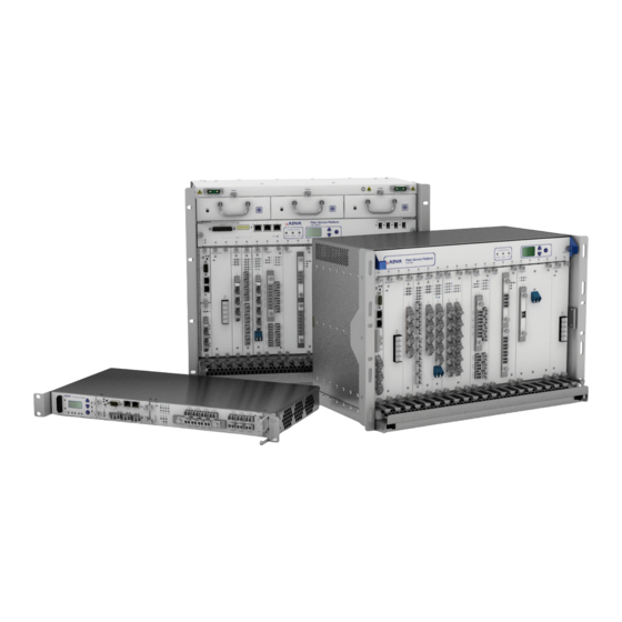
Adva FSP 3000R7 Maintenance And Troubleshooting Manual (1135 pages)
Fiber Service Platform
Brand:
Adva
| Category:
Network Hardware
| Size: 15 MB
Table of Contents
Replacing an N Port Pluggable Transceiver with a Different Type - Method
1
Replacing an N Port Pluggable Transceiver with a Different Type - Method
2
Table of Contents
3
Related Documents Overview
11
Planning
11
Provisioning and Operating
12
Working with Management Tools
12
Troubleshooting
13
Preface
15
Purpose and Scope
16
Audience
16
Documentation Revision History
16
Typographic Conventions
23
Document Conventions
23
Safety Symbol and Message Conventions
24
Obtaining Documentation
25
Documentation Feedback
25
Obtaining Technical Assistance
25
World Wide Web
25
Contact ADVA Optical Networking
26
Customer Portal
26
Technical Services
26
Preparation for Troubleshooting
29
Requirements
30
Required Personnel
30
Recommended Equipment
30
Cleaning and Inspecting Fibers and Ports
32
General Reminders and Warnings
33
Best Practices
34
Required Tools
34
Cleaning Fiber-Optic Connector Plugs
34
Cleaning and Inspecting Connector Receptacles
37
Cleaning and Inspecting Fiber Jumpers
38
Dry Cleaning Technique Using Cartridge and Pocket-Style Cleaners
38
Dry Cleaning Technique Using Lint-Free Wipes
40
Cleaning the End of a Jumper with a Clean-Room Tissue
41
Wet Cleaning Technique Using Lint-Free Wipes
41
Wet Cleaning Using Lint-Free Swabs
42
Dry Cleaning Using Lint-Free Swabs
43
Cleaning MTP Fiber Cable Ends
44
Vendor-Specific Cleaning Techniques
44
Cleaning Recommendation for Optical Ports of Pluggable Transceivers
45
Handling Equipment
47
Handling a Shelf
47
Handling Modules
48
Handling Pluggable Transceivers
49
Handling Fiber-Optic Cables
50
Optical Fiber Requirements
51
Connector Loss
51
Proper Cleaning and Connection
51
Return Loss
51
Periodical Maintenance
52
Finding Your Problem - Follow the Light
53
Shelves and Power Supply Units
59
Troubleshooting Shelves
60
SH1HU-F/2DC, SH1HU-HP/2DC and SH1HU-HP/E-TEMP/2DC Shelf Leds
60
SH1HU-F/2DC, SH1HU-HP/2DC, and SH1HU-HP/E-TEMP/2DC Fan Status LED
62
SH1HU-F/2DC, SH1HU-HP/2DC, and SH1HU-HP/E-TEMP/2DC Slot Status Leds
63
SH1HU-F/2DC, SH1HU-HP/2DC, and SH1HU-HP/E-TEMP/2DC Power Status Leds
65
SH1HU-F/2DC, SH1HU-HP/2DC, and SH1HU-HP/E-TEMP/2DC Network Element Status Leds
66
SH1HU-R(/PF) Shelf Leds
68
SH1HU-R Front Panel LED Indicators
68
SH1HU-R/PF Front Panel LED Indicators
68
SH1HU-R(/PF) Fan Status LED
69
SH1HU-R(/PF) Slot Status Leds
70
SH1HU-R(/PF) Power Status Leds
72
SH1HU-R(/PF) Network Element Status Leds
73
SH7HU(-R) Shelf Leds
75
SH7HU Fan Unit LED Indicators
75
SH7HU Versus SH7HU-R
75
SH7HU(-R) Fan Status Leds
76
SH7HU(-R) Slot Status Leds
77
SH7HU(-R) Network Element Status Leds
79
SH9HU and SHX9HU Shelf Leds
81
SH9HU Shelf LED Indicators
81
SH9HU and SHX9HU Fan Status Leds
82
SH9HU Fans (FAN/9HU)
82
LED Status of the FAN/9HU and FAN/X9HU
83
SH9HU and SHX9HU Slot Status Leds
83
SH9HU and SHX9HU Network Element Status Leds
85
OTDR Shelf Leds
87
LED Indicators of the OTDR
87
Troubleshooting Power Supply Units
88
PSU/1HU-R-AC and PSU/1HU-R
89
LED Status of the PSU/1HU-R-AC(-200) and PSU/1HU-R-DC-200
89
PSU/7HU-AC and PSU/9HU-AC
90
LED Status of the PSU/7HU-AC and PSU/9HU-AC
90
PSU/7HU-DC, PSU/7HU-DC-HP, PSU/7HU-DC-800, PSU/X9HU-DC-800, and PSU/9HU-DC
91
Psu/7Hu-R-DC
92
LED Status of the PSU/7HU-R-DC(-HP)
93
Core Type Channel Modules
95
Troubleshooting Core Type TDM Channel Modules
96
4Tcc-Pcn-2G1U+2G5
97
LED Status of the 4TCC-PCN-2G1U+2G5
98
4Tcc-Pctn-2G7+10G
104
LED Status of the 4TCC-PCTN-2G7+10G
105
4Tcc-Pctn-10G+40G-L#DC
111
LED Status of the 4TCC-PCTN-10G+40G-L#DC
112
10Tcc-Pcn-2G7Us+10G
120
LED Status of the 10TCC-PCN-2G7US+10G
121
10Tcc-Pctn-4Gu(S)+10G
127
LED Status of the 10TCC-PCTN-4GU(S)+10G
128
10TCC-PCTN-10G+100GB and 10TCC-PCTN-10G+100GC
134
LED Status of the 10TCC-PCTN-10G+100GB/C
135
10Tcc-Pcn-3Gsdi+10G
143
LED Status of the 10TCC-PCN-3GSDI+10G
144
10Tcc-Pcn-40Gu+100G
150
LED Status of the 10TCC-PCN-40GU+100G
151
16Tcc-Pcn-4Gus+10G
157
LED Status of the 16TCC-PCN-4GUS+10G
158
Troubleshooting Core Type WDM Channel Modules
165
2Twcc-Pcn-2G7U
166
LED Status of the 2TWCC-PCN-2G7U
167
2Wcc-Pcn-10G
173
LED Status of the 2WCC-PCN-10G
174
4Wcc-Pcn-10G
180
LED Status of the 4WCC-PCN-10G
181
Wcc-Pc1N-2G7U
187
LED Status of the WCC-PC1N-2G7U
188
Wcc-Pctn-10G
194
LED Status of the WCC-PCTN-10G
195
Wcc-Pctn-100G(A,B)
202
LED Status of the WCC-PCTN-100GA/WCC-PCTN-100GB
203
Wcc-Pcn-100G
210
LED Status of the WCC-PCN-100G
211
Wcc-Tn-40G-L#DC
220
10Wxc-Pcn-10G
226
LED Status of the 10WXC-PCN-10G
227
Access Type Channel Modules
231
Troubleshooting Access Type TDM Channel Modules
232
2Pca-Pcn-10G
233
LED Status of the 2PCA-PCN-10G
234
2Tca-Pcn-1G3+2G5
239
LED Status of the 2TCA-PCN-1G3+2G5
240
2Tca-Pcn-622M+2G5
246
LED Status of the 2TCA-PCN-622M+2G5
247
4Tca-Ls+1G3-V
252
LED Status of the 4TCA-LS+1G3-V
253
4Tca-Pcn-4Gu(S)+4G
257
LED Status of the 4TCA-PCN-4GU(S)+4G
258
8Tca-Pc-2G1U+10G-V
264
Different Groups Configured to Different Data Rates
265
LED Status
265
Mixtures of Data Rates
265
Supported Data Rates
265
LED Status of the 8TCA-PC-2G1U+10G-V
266
10Pca-Pcn-1G3+10G
270
LED Status of the 10PCA-PCN-1G3+10G
271
Troubleshooting Access Type WDM Channel Modules
276
2Wca-Pcn-10G
277
LED Status of the 2WCA-PCN-10G
278
Wca-Pc-10G-V
281
LED Status of the WCA-PC-10G-V
282
Wca-Pcn-2G5U
286
LED Status of the WCA-PCN-2G5U
288
5Wca-Pcn-16Gu
297
LED Status of the 5WCA-PCN-16GU
298
Enterprise Type Channel Modules
301
Troubleshooting Enterprise Type TDM Channel Modules
302
5Tce-Pctn-8Gu+(Aes)10Gs
303
LED Status of the 5TCE-PCTN-8GU+(AES)10GS
304
5Tce-Pcn-8Gu+(Aes)10Gs
312
LED Status of the 5TCE-PCN-8GU+(AES)10GS
313
5Tce-Pctn-10Gu+(Aes)10G
321
LED Status of the 5TCE-PCTN-10GU+(AES)10G
322
5Tce-Pcn-10Gu+(Aes)10G
330
LED Status of the 5TCE-PCN-10GU+(AES)10G
331
8Tce-Escon+2G5-V
339
8Tce-Glink+2G5-V
343
LED Status of the 8TCE-GLINK+2G5-V
344
10Tce-Pcn-10G+100G(-Gf)
347
LED Status of the 10TCE-PCN-10G+100G(-GF)
348
10TCE-PCN-16GU+(AES)100G and 10TCE-PCN-16GU+AES100G-BSI
353
Troubleshooting Enterprise Type WDM Channel Modules
368
Wce-Pcn-100G(B)
369
LED Status of the WCE-PCN-100G
370
4Wce-Pcn-16Gfc
377
LED Status of the 4WCE-PCN-16GFC
378
Management and Switch Modules
385
Troubleshooting Management Modules
386
Ncu
386
LED Indicators and Reset Button of the NCU (NCU2E)
386
LED Indicators and Reset Button of the NCU-II
387
Troubleshooting Serial Connection Issues
387
Troubleshooting Ethernet Connection Issues
388
Troubleshooting NCU Configuration Issues
389
LED Status of the NCU
390
NCU LED Status
390
LED Status of the NCU-II-P
392
Ncu-II-P
392
LED Status of the NCU-S
394
Ncu-S
394
Scu
396
Scu-II
399
LED Status of the SCU-II
399
Scu-S
401
LED Status of the SCU-S
402
Oscm
403
LED Status of the OSCM
404
UTM and UTM-S
405
LED Status of the UTM and UTM-S
406
Pscu
408
LED Status of the PSCU
408
Cem/9Hu
411
LED Status of the CEM/9HU
411
Troubleshooting Switch Modules
414
Oppm
415
LED Status of the OPPM
415
Vsm
418
LED Status of the VSM
418
Rsm-Olm#1630
420
LED Status of the RSM-OLM#1630
421
Rsm-Sf
423
LED Status of the RSM-SF
424
Reconfigurable Optical Layer Devices
425
Roadm-C40/40/Opm-3Hu/2Dc
426
ROADM-C40/40/OPM-3HU/2DC LED Indications
426
ROADM and CCM Modules
429
ROADM Module LED Indications
429
4-Opcm
434
4-OPCM LED Indications
434
Passive Optical Filter Module Types
437
Optical Filters (Passive Modules and Shelves)
437
Optical Amplifiers
441
Fixed Pump-Power EDFA Modules
442
LED Status of Fixed Pump-Power EDFA Modules
442
Fixed Gain-Controlled EDFA Modules
444
Fixed Gain-Controlled, Single-Stage EDFA Modules
445
LED Status of Single-Stage, Fixed Gain-Controlled EDFA Modules
445
Fixed Gain-Controlled, Double-Stage EDFA Modules
447
LED Status of Double-Stage, Fixed Gain-Controlled EDFA Modules
447
Variable Gain(-Controlled) EDFA Modules
451
Variable Gain-Controlled EDFA Modules
452
LED Status of the EDFA-C-D20 Modules
453
Variable-Gain EDFA Modules
458
RAMAN-C10 Module
459
LED Status of the RAMAN-C10 Module
460
2RAMAN-C15-LL Module
467
LED Status of the 2RAMAN-C15-LL Module
468
AMP-S20H-C15 and AMP-S20L-C15 Modules
475
LED Status of the AMP-S20H-C15 and AMP-S20L-C15 Modules
476
EDFA-S20H and EDFA-S20L Modules
486
LED Status of the EDFA-S20H and EDFA-S20L Modules
487
2EDFA-S20L-S10L Modules
495
LED Status of the 2EDFA-S20L-S10L Modules
496
Dispersion Compensation Modules
507
LED Status of the Dispersion Compensation Modules
508
NCU Troubleshooting
509
Viewing IP Addresses
510
Setting NCU Passwords to Default Values
511
About Default Passwords
511
Resetting Passwords in First Generation Ncus
512
Boot Loader Output of a First Generation NCU
513
Resetting Passwords in Second Generation Ncus
514
Boot Loader Output of a Second Generation NCU
515
Controlling Boot Loader Access
516
Restarting the NCU
517
Warm-Starting the NCU
517
Cold-Starting the NCU
518
Example of the Reset Button on the NCU2E Faceplate
519
Deleting the Active Database
520
Replacing the NCU Compact Flash
521
Removing the NCU Compact Flash
521
NCU Placement for Compact Flash Card Removal
522
Remove the Locking Plate from the Slot
522
Unlock the Compact Flash Card
522
Installing Compact Flash in an NCU
523
Remove the Compact Flash Card from the Slot
523
Insert the Compact Flash Card into the Slo
524
Placement of the NCU for Inserting the Compact Flash Card
524
Lock the Compact Flash Card by Inserting the Locking Plate
525
Replacing an NCU
526
Considerations When Replacing a Malfunctioning NCU
526
Basic Requirements
527
Connection Scenarios
527
Considerations When Replacing an NCU with a Newer Type
527
Required Information
527
NE, Management, and FTP Server Connection Options
528
Required Equipment
529
NCU Replacement Scenarios
530
Replacing a Malfunctioning NCU
530
Removing an NCU Module from Slot a of an SH7HU Shelf
532
Inserting an NCU into Slot a of an SH7HU Shelf
534
Replacing a First Generation NCU with an NCU-II
537
Control Plane Maintenance and Troubleshooting
543
Maintaining Tunnels and Services
544
Converting an Existing Service to Control Plane Management
544
About WDM Cross-Connections
548
Building WDM Cross-Connections
549
Converting a Service from Control to Management Plane Ownership
550
Repairing Tunnels after Replacing a Network Element
551
Viewing Traffic Engineering Information in an NE
555
Viewing te Router Information
556
Viewing te Link Information
557
Manually Restoring a Path
559
Troubleshooting Control Plane Issues
560
Checking Status of te Links
560
Verifying List of te Routers
560
Checking Synchronization Status of te Links
561
Verifying Logical Interfaces
562
Verifying Physical Connections
562
Checking OSPF Settings
563
Verifying All Nodes Are Listed
563
Ensuring the Correct Topology
564
Verifying OSPF Neighbors
565
Resolving Connection Failures Resulting from MTU Size Mismatches
566
OSPF Neighbors of the NE
566
MTU Size Comparison
567
OSPF Neighbors of the BDR
567
Tracing a Channel through the Node
568
General Module and Management Configuration
569
Configuring SNMP Settings
570
Configuring In-Band Management
571
In-Band Management on Channel Modules
571
In-Band Management Configuration Example
571
Example of Configuring the ECC
572
Example of Configuring the NCU
573
Example of Disabling the Far-End LAN IP Interface
574
Example of Verifying Connectivity
574
Configuring Loopbacks
575
Configuring a Client Interface Loopback
576
Configuring a Network Interface Loopback
576
Configuring Clock Speeds
578
Setting Auto Laser Shutdown
579
Forcing and Releasing Lasers
581
Checking for Higher-Level NTP Servers
583
Configuring an OSCM
584
Configuring OSPF
585
Tracking a Channel in a Node
586
Tracking a Channel through a Node
586
Track Channel
587
Configuring Trace Monitoring
589
Configuring SONET/SDH Traces
589
Configuring OTN Traces
590
Configuring Wavelengths
593
Reconfiguring Wavelengths
593
Restarting Modules
595
Cold Restart
595
Warm Restart
595
Exporting Network Element Logs
597
Configuring Equipment Capabilities
598
Increasing Capability
598
Viewing Capability Level
598
Updating Software, Firmware, and Database
601
About Software and Database Files
602
The Software Package
602
Handling of Files
603
Software and Database Compatibility
604
Software Update and Switchback
604
NE Software Activation Keeping Current Database
605
NE Software Update, First-Time Activation
605
Switchback to Previous NE Software and Database
605
About NE Software Version and File Names
606
Database Restoration Guidelines for Control Plane Users
607
Fixing Corrupted Database on a Single NE
607
Case 1: Signaling State for Tunnel Is Present in the Network, but the Restored Database Has no Knowledge of It
607
Case 2: Restored Database Has a Tunnel Marked "In-Service", but no Signaling State (Connections) Is Present in the Network
607
Ideal Case
607
Array
608
Case 3: Restored Database Has a Tunnel Marked "In- Service", Signaling State for the Tunnel Is Present, but the Connections in the Database Do Not Mat
608
Provisioning a Green-Field Network
609
Backing up and Restoring the Database
610
Backing up the Database
610
Backing up the Database at a Scheduled Time
611
Viewing Files Stored on the NE
613
Restoring the Database
614
Viewing Module Firmware Versions
616
Updating the NE Software Release
617
Transferring Software to the NCU
620
Transferring Firmware Packages to All Modules (Native)
621
Activating Software
623
Scheduling Software Activation
624
Transferring and Activating Firmware on All Modules
625
Performing Other Software Update Actions
628
Reverting to the Previous Software Release
628
Updating Modules with Encryption
628
Enabling Update of Modules with Encryption
629
Updating Encryption Module Firmware
629
Updating HD Module Firmware
630
Updating a Module
631
Updating Modules of the same Type
632
Transferring Files To/From the NE
633
Uploading Files from the NCU
633
Downloading Files to the NCU
634
Downloading Files from the SCU to the NCU
635
Performance Management
637
Introduction
638
Performance Monitoring at the Physical Layer
639
Recorded Measurements
639
Real Time Measurements
640
Physical Layer Counter
641
Instantaneous Measurement Parameters
641
Performance Monitoring at the Data Layer
642
SDH/SONET Performance
643
SDH/SONET Counter Descriptions
643
OTN Performance
644
Physical Coding Sublayer (PCS) Performance
644
OTN and FEC Counter Descriptions
644
Sub-Aggregate Layer Performance
645
PCS Counter Descriptions
645
Sub-Aggregate Layer Counter Descriptions
645
Ethernet Performance
646
Ethernet Counter Descriptions
646
GFP Frame Performance
648
Framed GFP Frame Counter Descriptions
648
Transparent GFP Frame Counter Descriptions
648
EVC Frame Performance
649
Counter Descriptions Per EVC, at Receive
649
Counter Descriptions Per EVC, at Transmit
649
Performance Records
650
Record Types
650
Current 15-Minute Record
650
History 15-Minute Record
650
Record Content
651
Current 1-Week Record
651
History 1-Week Record
651
Record Validity
651
Record Storage
652
Saving Performance Monitoring History Records
652
Exchanging Equipment
653
Before Exchanging Equipment
654
Replacing an Optical Module
656
Removing an Optical Module
656
Removing a Channel Module from an SH1HU Shelf Slot
659
Installing an Optical Module
660
Equipment Required
661
Adding Procedure
662
Replacing an Encryption Module
668
Removing an Encryption Module
668
Installing an Encryption Module
671
Replacing a Raman Amplifier
676
Replacing Pluggable Transceivers
677
General Information
677
Safety Guidelines
678
Removing an SFP or XFP Transceiver
679
Example of an XFP Transceiver Prepared for Extracting
681
Installing an SFP or XFP Transceiver
682
Example of an XFP Dust Plug Inserted into an Empty XFP Cage
682
Example of a Dust Plug Covering an XFP Cage
684
Example of an XFP Transceiver Prepared for Inserting
685
Removing a CFP Transceiver
686
Example of Removing CFP Transceiver from Channel Module Interface Cage
688
Installing a CFP Transceiver
689
Example of a CFP Dust Plug Inserted into an Empty CFP Cage
689
Example of a CFP Dust Plug Covering a CFP Cage
691
Check the Corresponding Channel Module Port LED
692
Example of Inserting a CFP Transceiver
692
Replacing Pluggable Transceivers in a Control Plane-Based Network
694
Replacing an N Port Pluggable Transceiver with the same Type
694
Replacing an N Port Pluggable Transceiver with a Different Type - Method 1
695
Replacing a C Port Pluggable Transceiver
696
Replacing Power Supply Units
697
General Information
697
Replacing a PSU/1HU-R-AC(-200) or PSU/1HU-R-DC-200
699
Replacing a PSU/7HU-AC, PSU/7HU-AC-HP, or PSU/7HU
704
Replacing a PSU/7HU-DC, PSU/7HU-DC-HP, or PSU/7HU
709
PSU/7HU-DC and PSU/7HU-DC-HP
715
Replacing a PSU/7HU-R-DC or PSU/7HU-R-DC-HP
716
Replacing a PSU/9HU-DC, PSU/X9HU-DC-800, or PSU/9HU-AC
721
Replacing, Upgrading, or Downgrading Psus in a Mixed PSU Configuration
726
PSU Power Requirements During Insertion and Removal
733
PSU in Slot 19/20 Being Replaced or Upgraded
735
PSU in Slot 1/2 Being Replaced or Upgraded
736
Replacing Fan Units and Fan Modules
737
Front View of the SH7HU Fan/Plug-In
737
Pressing down of the Blue Levers
738
Pulling out the Unit
738
Front View of the SH7HU(-R) Fan Unit Removed from Housing
739
Replacing a FAN/9HU or FAN/X9HU
739
FAN9HU Front View
740
Replacing a FAN/1HU
742
Screws Holding the Display Front Panel to the Shelf
743
Removing the Fan Module from the Shelf Slot
744
Replacing Air Filter Pads
746
Replacing a PSU/1HU-R-AC-200 Air Filter Pad
746
Front View of the Air Filter Unit
746
Replacing a 7HU/9HU-Shelf Air Filter Pad
747
Air Filter Pad Removed from the PSU/1HU-R-AC-200
747
Five Slots at the Rear Part of the Air Filter Unit
748
Removing an Air Filter Pad
749
Replacing the SH1HU-R/PF Shelf Air Filter Pad
749
Air Filter Frame Unlocked
750
Front View of the SH1U-R/PF Air Filter Unit
750
Pulling out the Air Filter Pad
751
Replacing an SH1HU Shelf
752
Example of an SH1HU Shelf Front View (SH1HU-HP/2DC)
754
Power Supply of the SH1HU-F/2DC Shelf
754
Sh1Hu-F/2Dc
754
SH1HU-HP/2DC and SH1HU-HP/E-TEMP/2DC
755
Sh1Hu-R
755
SH1HU-R Rear View
755
Power Cord Attached to the PSU/1HU-R-AC
756
Grounding Conductor Shown with Ring Lug and Two-Hole Lug
758
Grounding Conductor with Faston Wire Receptacle
758
Replacing an SH7HU(-R), SHX9HU, or SH9HU Shelf
759
Final Steps When Replacing a Master Shelf
760
Final Steps When Replacing a Main Shelf
761
Replacing a 40CSM/2HU Shelf
763
Removing and Mounting Front Covers
768
Removing an SH7HU, SH9HU, or SHX9HU Front Cover
768
Removing the Front Cover
769
Mounting an SH7HU, SH9HU, or SHX9HU Front Cover
769
Equipment and Tools Required
770
Positioning the Front Cover
770
Removing the 40CSM/2HU Front Cover
770
Mounting the 40CSM/2HU Front Cover
771
Mounting a Front Cover to a 40CSM/2HU Shelf
772
Removing and Inserting a Dummy Module
773
Inserting a Dummy Module
773
Removing a Dummy Module
775
Removing a Dummy Module from a Shelf Slot
776
Generating a Support Data File
777
Collecting Support Data Using NED
778
Collecting Support Data Using Shell
779
Advertisement
Adva FSP 3000R7 Installation And Commissioning Manual (378 pages)
Fiber Service Platform
Brand:
Adva
| Category:
Network Hardware
| Size: 12 MB
Table of Contents
Table of Contents
3
List of Figures
13
List of Tables
17
Related Documents Overview
19
Troubleshooting
21
Audience
23
Preface
23
Purpose and Scope
23
Document Revision History
24
Organization
25
Acronyms and Abbreviations
26
Document Conventions
27
Typographic Conventions
27
Safety Symbol and Message Conventions
28
Obtaining Documentation
29
World Wide Web
29
Documentation CD
29
Ordering Documentation
29
Documentation Feedback
30
Obtaining Technical Assistance
30
Customer Portal
30
Technical Services
31
Contact ADVA Optical Networking
31
Acronyms and Abbreviations
33
Chapter 1 Express Setup
43
Figure 1: Installation Flowchart
44
Chapter 2 Prerequisites for Installation
45
Audience
46
Safety Precautions
46
General Safety
46
Electrical Safety
47
Eye Safety
49
Laser Safety
49
Operating Conditions
50
Equipment Precautions
51
Facility Security
52
Personnel Requirements
52
Supporting Documents and Additional Information
53
Supplies and Tools Required
54
Adaptor Brackets
54
Dummy Modules
54
Front Cover
55
Power Cables
55
Earthing Kit
55
Serial and Ethernet Cables
55
IEEE 1394 Interface Cable
55
Telemetry Interface Cable
56
SCU-Intercom-Kit
56
Fiber-Optic Jumpers
56
Tools and Equipment Required
56
Tools
56
Electrical Test Equipment
56
Fiber Optic Test and Cleaning Equipment
57
ESD Prevention Equipment
57
Personal Computer
57
Commissioning Information
57
Chapter 3 Site Planning and Preparation
59
Introduction
59
Audience
60
Site Planning
60
General Site Requirements
61
FSP 3000R7 Equipment Requirements
61
Compliance Criteria
61
Specifications of System Components
62
Table 1: Dimensions and Weight of the System Components
62
Clearance Requirements
63
Environmental Requirements
63
Table 2: Minimum Clearance Requirements
63
Cooling Requirements
64
Heat Dissipation
64
Airflow Considerations
64
Power Source and Earthing Requirements
65
Shelf Power System
65
General Requirements for the Site Wiring Systems
66
DC Power Requirements
67
Table 3: Power Ratings for DC-Powered 9HU and 7HU Shelves
67
Table 4: Power Ratings for DC-Powered 1HU Equipment Shelves
67
AC Power Source Requirements
68
Table 5: Electrical Requirements for the AC-Powered 7HU Shelf and 9HU Shelf
68
Power Cable Requirements
69
DC Power Cables
70
Table 6: DC Power Cable Minimum Requirements
70
AC Power Cables
71
Table 7: AC Power Cable Minimum Requirements
71
System Earthing Conductor Requirements
72
Serial Cable and Ethernet Cable Requirement
72
Table 8: Serial and Ethernet Cable Types
72
Serial Null Modem Cable
73
Table 9: Wiring for Serial Null Modem Cable
73
Ethernet Straight-Through Cables and Crossover Cables
74
Table 10: Ethernet Cable Types Used by the FSP 3000R7
74
Table 11: Wiring for 10BASE-T and 100BASE-TX Straight through and Crossover Cables
75
Table 12: Wiring for 1000Base-T Straight-Through Cable According to 568B
75
Table 13: Wiring for 1000Base-T Crossover Cable According to 568B
76
Table 14: Standard USB Type a Plug Pinout
77
Table 15: Mini-USB Type a Plug Pinout and Cable Color Code
77
Telemetry Interface Cable
77
USB Cable
77
IEEE 1394 Interface Cable
78
SCU-Intercom-Kit
78
Table 16: Female HD SUB-D44 Connector Pinout
78
Fiber-Optic Cable Requirements
79
Fiber-Optic Jumpers
79
Client Interface Fiber-Optic Patch Cables
79
Network Interface Fiber-Optic Patch Cables
79
Optical Fiber Bundles
80
Optical Link Testing
80
Cabling Requirements
80
Requirements for Installing the OTDR
80
Power Supply Requirements
80
Table 17: Network Span Tests
80
Earthing Conductor Requirements
81
Power Cable Requirements
81
Table 18: AC Power Cable Requirements
81
Data Cable Requirements
82
Fiber-Optic Cable Requirements
82
Site Preparation
82
Shared Responsibilities
82
Table 19: Data Cable Requirements
82
ADVA Optical Networking Responsibilities
83
Customer Responsibilities
83
Checking the Site
84
Specialized Knowledge Required
84
Tools Required
84
Associated Documentation
85
Site Survey Checklist
85
Table 20: Site Survey Checklist
85
Chapter 4 Unpacking and Inspecting
89
Introduction
90
Table 21: Outer Dimensions and Average Weight of the FSP 3000R7 Equipment Shelf Shipping Boxes
90
Table 22: Outer Dimensions and Average Weight of Other FSP 3000R7 Shipping Boxes
90
Audience
91
Associated Documentation
91
Precautions
91
Temporary Storage
92
Moving to the Installation Location
92
Lifting and Carrying the 9HU Shelf or 7HU Shelf
92
Preventing ESD Damage
93
Shipment Contents and Accessories
94
1HU Shelf, 7HU Shelf and 9HU Shelf Shipments
94
Table 23: 1HU Shelf, 7HU Shelf and 9HU Shelf Shipments
94
DCM Shelf, Passive Shelf and Fiber Management Shelf Shipments
96
Table 24: SH1HU/PASSIVE Shelf Shipment
96
Unpacking a 7HU Shelf
97
Table 25: DCF1HU-P Shelf Shipment
97
Table 26: SH1HU/FIBERMANAGEMENT Shelf Shipment
97
Figure 1: Unpacking the 7HU Shelf
98
Unpacking a 1HU Shelf
100
Unpacking a DCM Shelf
101
Unpacking a Module-Integrated DCM Shelf
104
Unpacking an 1HU Passive Shelf
106
Unpacking an FSP 3000R7 ROADM-C40/40/2-3HU-2DC Shelf
107
Unpacking an SH1HU/FIBERMANAGEMENT Shelf and an FMT/1HU Shelf
109
Figure 2: Unpacking a Fiber Management Shelf (FMT/1HU Shelf)
110
Inspecting an FSP 3000R7 Shelf
111
Additional Information
112
Identifying Modules
114
Figure 3: Example of Type Designations on the SCU Faceplate
115
Figure 4: Example of a SCU Module Type Label
115
Identifying Pluggable Transceivers
116
Figure 5: Example of a DWDM SFP Transceiver Type Label
117
Inspecting the FSP 3000R7 ROADM-C40/40/2-3HU-2DC Shelf
118
Equipment Return and Repair
119
Shipping Instructions
120
Chapter 5 Installing Shelves
121
Introduction
122
Audience
123
Associated Documentation
123
Installing the SH9HU, SH7HU, SH7HU-R and 1HU Equipment Shelves
124
Fitting the ESD Connection Adaptor to a Shelf Bracket
124
Figure 6: ESD Adaptor Pack
125
Figure 7: Front Cover Attached to the SH7HU
125
Fitting the 9HU, 7HU Shelves and 1HU Equipment Shelves with ETSI or NEBS Brackets
127
Figure 8: Attached ESD Connection Adaptor
127
Fitting a 9HU Shelf with ETSI or NEBS Brackets
128
Figure 9: ETSI and NEBS Adaptor Brackets for a 9HU Shelf
129
Figure 10: Front Cover Fixing Bracket on the 19'' Bracket
130
Figure 11: Fitting the ETSI and NEBS Adapter Brackets to an 9HU Shelf
131
Fitting a 7HU Shelf with ETSI or NEBS Brackets
131
Figure 12: ETSI and NEBS Adaptor Brackets for a 7HU Shelf
132
Figure 13: Front Cover Fixing Bracket
133
Figure 14: Fitting the ETSI and NEBS Adopter Brackets to an 7HU Shelf
134
Fitting the 1HU Equipment Shelves with ETSI or NEBS Brackets
134
Figure 15: ETSI and NEBS Adaptor Brackets for a 1HU Shelf
135
Figure 16: Fitting an 1HU Shelf with an ETSI Bracket
136
Figure 17: Fitting an 1HU Shelf with an NEBS Bracket
136
Fitting the SH1HU-R/PF with ETSI or NEBS Brackets
137
Figure 18: ETSI and NEBS Adaptor Brackets for a SH1HU-R/PF
138
Figure 19: Fitting the ETSI and NEBS Adopter Brackets to an SH1HU-R/PF Shelf
139
Earthing a Shelf
140
Connecting a Shelf to Earth
142
Mounting an FSP 3000R7 Shelf into a Rack or Cabinet
144
Figure 20: Example of Connecting an Functional Earthing Conductor with a Ring Lug to a 7HU Shelf
144
Figure 21: Example of Connecting an Functional Earthing Conductor with Two Hole Lug Terminal to a 7HU Shelf
144
Figure 22: Example of Connecting an Functional Earthing Conductor with Faston Wire Receptacle to a 7HU Shelf
144
Figure 23: Example of a Six-7HU Shelf System
145
Figure 24: Example of 7HU Shelves Mounted into in a 19-Inch Open Rack
149
Connecting the Power
150
Connecting DC Power
150
Figure 25: Connecting the Power Cable to the 9HU Shelf on the Front
156
Figure 26: Connecting the Power Cable to the SH7HU-R
159
Figure 27: Connecting the Power Cable to the SH1HU-HP/2DC
162
Figure 28: Connecting a DC Power Cord to a PSU of the SH7HU
166
Figure 29: Connecting the Power Cords to the Power Supply of the SH1HU-F/2DC Shelf
167
Figure 30: Mounting the Tab Connectors to a PSU of the SH7HU
167
Figure 31: Attaching the Terminal Flags to the Tab Connectors Mounted to the PSU of the SH7HU
168
Connecting AC Power
172
Figure 32: Assembling the Power Cord Locking Clamp to the AC Power Supply
175
Figure 33: Example of Connecting the AC Power Cord to the PSU of the SH7HU and SH1HU-R
175
Installing a 40CSM/2HU Shelf
177
General Information
177
Fitting the 40CSM/2HU Shelf with the FIBER FINGER/2HU or FIBER FINGER/2HU LEFT
178
Figure 34: Example of Attaching the FIBER FINGER/2HU to a 40CSM/2HU Shelf
180
Figure 35: Example of Attaching the FIBER FINGER/2HU LEFT to the 40CSM-FL/2HU-#19590-#19200 Shelf
180
Fitting the 40CSM/2HU Shelf with 19-Inch Brackets
181
Figure 36: 19-Inch Bracket for a 40CSM/2HU Shelf
181
Fitting the 40CSM/2HU Shelf with ETSI Brackets
182
Figure 37: 19-Inch Bracket Fitted to the 40CSM/2HU-#D02-#D32 Shelf
182
Figure 38: ETSI Bracket for an 40CSM/2HU Shelf
183
Fitting the 40CSM/2HU Shelf with NEBS Brackets
184
Figure 39: ETSI Bracket Fitted to the 40CSM/2HU-#D02-#D32 Shelf
184
Figure 40: NEBS Bracket for a 40CSM/2HU Shelf
185
Mounting the 40CSM/2HU Shelf into a Rack
186
Figure 41: NEBS Bracket Fitted to the 40CSM/2HU-#D02-#D32 Shelf
186
Rack-Mounting the 1HU Passive Shelf
187
Specialized Knowledge Required
188
Fitting the 1HU Passive Shelf with Adaptor Brackets
188
Figure 42: Adaptor Bracket Installation - Front Mounted
190
Figure 43: Adaptor Bracket Installation - Rear Mounted
191
Figure 44: Example of 19-Inch Bracket Attachment - Front Mounted (Left)
192
Mounting the 1HU Passive Shelf into a Rack or Cabinet
193
Figure 45: Example of ETSI Bracket Attachment - Front Mounted (Left)
193
Figure 46: Example of NEBS Bracket Attachment - Front Mounted (Left)
193
Rack-Mounting the DCF1HU-P Shelf
195
Specialized Knowledge Required
195
Fitting the DCF1HU-P Shelf with 19-Inch, NEBS or ETSI Brackets
195
Figure 47: 19-Inch, NEBS and ETSI Brackets for a DCF1HU-P Shelf
197
Figure 48: 19-Inch Bracket Fitted to the DCF1HU-P Shelf
198
Figure 49: NEBS Bracket Fitted to the DCF1HU-P Shelf
198
Figure 50: Customized ETSI Bracket Fitted to the DCF1HU-P Shelf
198
Mounting the DCF1HU-P to an Rack or Cabinet
199
Figure 51: ETSI Bracket Fitted to the DCF1HU-P Shelf
199
Rack-Mounting the SH1HU/FIBERMANAGEMENT and the FMT/1HU Shelf
202
Specialized Knowledge Required
202
Fitting the SH1HU/FIBERMANAGEMENT with 19-Inch Brackets
202
Figure 52: Example of an ETSI Bracket for a Fiber Management Shelf
203
Fitting the SH1HU/FIBERMANAGEMENT with NEBS Brackets
204
Figure 53: ETSI Bracket Mounted for 19-Inch to the Shelf
204
Figure 54: Example of One NEBS Bracket for a Fiber Management Shelf
204
Fitting the FMT/1HU with ETSI Brackets
205
Figure 55: NEBS Bracket Mounted to the Shelf
205
Figure 56: ETSI Adaptor Brackets for a FMT/1HU
206
Mounting the SH1HU/FIBERMANAGEMENT or the FMT/1HU into a Rack or Cabinet
207
Figure 57: Fitting an FMT/1HU with an ETSI Bracket
207
Installing Fiber Optic Cables
209
Figure 58: Example of a Fiber Management Shelf Mounted into a 19-Inch Open Rack
209
Figure 59: Example of a Cable Configuration in the Fiber Optic Tray of an SH1HU/FIBERMANAGEMENT
211
Installing the FSP 3000R7 ROADM-C40/40/OPM-3HU/2DC Shelf
212
Rack Mounting the FSP 3000R7 ROADM-C40/40/OPM-3HU/2DC Shelf
212
Figure 60: Typical ROADM-C40/40/2-3HU-2DC Shelf Location
213
Mounting a ROADM-C40/40/OPM-3HU/2DC Shelf into a Standard 19-Inch Rack
214
Figure 61: ROADM-C40/40/OPM-3HU/2DC Shelf Installed in a 19-Inch Rack
215
Mounting a ROADM-C40/40/OPM-3HU/2DC Shelf into a Standard 23-Inch Rack
216
Figure 62: Installing the 23-Inch Rack Adapter Brackets
217
Earthing the ROADM-C40/40/OPM-3HU/2DC Shelf
218
Connecting DC Power
219
Figure 63: Earthing Conductor Mounted to the ROADM-C40/40/OPM-3HU/2DC Shelf
219
Figure 64: DC Power Wires Installed on Terminal Block
220
Testing the Earth and DC Power Connections
221
Figure 65: Terminal Block with Cover Installed
221
Installing the OTDR
222
Verifying the Basic Installation
224
Advertisement
Related Products
Adva FSP 3000
Adva 3000R7
Adva Categories
Network Hardware
More Adva Manuals
Login
Sign In
OR
Sign in with Facebook
Sign in with Google
Upload manual
Upload from disk
Upload from URL