Sign In
Upload
Manuals
Brands
ADTRAN Manuals
Network Hardware
200410L1
ADTRAN 200410L1 Manuals
Manuals and User Guides for ADTRAN 200410L1. We have
1
ADTRAN 200410L1 manual available for free PDF download: User Manual
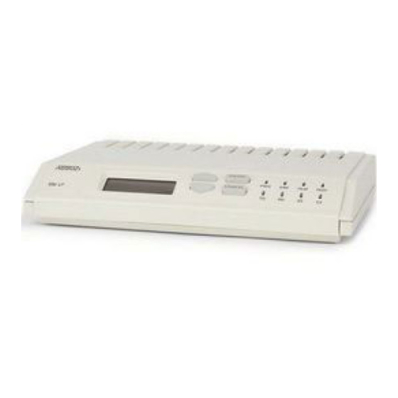
ADTRAN 200410L1 User Manual (92 pages)
ESU LT
Brand:
ADTRAN
| Category:
Network Hardware
| Size: 1 MB
Table of Contents
Important Safety Instructions
5
Warranty and Customer Service
7
Table of Contents
9
List of Figures
15
Chapter 1. Introduction
19
ESU LT Overview
19
Functional Description
19
Figure 1-1. ESU LT Unit - Front View
19
ESU LT Rear Panel
20
Figure 1-2. ESU LT Rear Panel
20
ESU LT Features
21
ESU LT Interfaces
21
Figure 1-3. ESU LT Interfaces
21
Chain Port Output
22
Control Port Input
22
Network Interface (NI)
22
Network Test Interface
22
Nx56/64 Serial Interface
22
Software Management
22
Front Panel
22
T-Watch Pro Management Software Program
23
ESU LT Testing
23
Self-Test
23
Figure 1-4. Network Loopback Tests
24
Loopback Tests
24
Network Loopbacks
24
Payload Loopback
24
DTE Interface Loopbacks
25
DTE Loopback
25
Figure 1-5. DTE Interface Loopback
25
Pattern Generation
26
Bridge/Router Application
27
Figure 1-6. Simple Bridge Application on a E1 or FE1 Circuit
27
Chapter 2. Installation
29
Inspecting for Shipping Damages
29
Items Shipped by ADTRAN
29
Items Provided by Customer
29
Power Connection
30
Power up Testing and Initialization
30
Chapter 3. Operation
31
Operation
31
General Menu Operation
31
Figure 3-1. ESU LT Main Menu
31
Menu Structure
32
Figure 3-2. ESU LT Main Menu Screen
32
Config
33
Curr Err/Alm
33
Err/Alm Hist
33
Four Opening Menu Functions
33
Network (Ni)
33
Ni Perf Rpts (Reports)
33
Port
33
Status
33
Unit
33
Util
33
Address
34
Fact Restore
34
Keypad
34
Network Tests
34
Reinit Unit
34
Run Self Test
34
Set Passcode
34
Software Rev
34
Test
34
Time/Date
34
Cancel Tests
35
Port Tests
35
Menu Features
35
Arrows
35
Data Field
35
Display Field
35
Example Menu Operations
35
To Select a Menu Item
35
Figure 3-3. Cursor on Menu Item
36
Figure 3-4. Submenu Fields
36
To Select a Submenu Item
36
To Exit any Menu Field Operation or Display
37
To Set the Data Field
37
To View Display-Only Data Fields
37
Front Panel
38
Figure 3-5. Front Panel Layout
38
Chapter 4. Status Menu
39
Status
39
Figure 4-1. Status Menu
39
Ni Perf Rpts
40
Bes
40
Figure 4-2. Severely Errored Seconds Scree
40
Reset Perf CNTRS
40
Ses
41
Uas
41
Curr Err/Alm
41
Ais Received
42
Alarms and Errors
42
Ext Clock Alarm
42
Loss of Crc-4
42
Loss of Frame
42
Loss of Signal
42
Loss of Ts16 Mf
42
Remote Alarm
42
Remote Mf Alarm
42
Ts16 Ais Rcv
42
E-Bit Error
43
Fas Word Error
43
Pll Alarm
43
ERR/ALM Hist
43
Figure 4-4. Clear History Screen
43
Chapter 5. Configuration Menu
45
Config
45
Figure 5-1. Configuration Menu
45
Network (NI)
46
Figure 5-2. Network Submenu
46
Interface
46
Cas/Ts16
47
Ccs
47
Framing
47
Unframed
47
Crc-4
48
Line Code
48
Nfas Word
48
Rfa Gen
48
Timing Mode
48
Figure 5-3. Network Timed Clock Source
49
Figure 5-4. Internal Timing Clock Source
49
Internal Timing
49
Network Timing
49
DTE Timing
50
Figure 5-5. DTE Clock Source
50
Figure 5-6. Configuration Submenu
50
Cntrl Port
51
Data Rate
51
Modem Init
51
Position
51
Alarms
52
Output
52
Tel Num
52
Traps
52
Unit
50
Port Config (Port Configuration)
53
Dte Tx Clock
53
Interface
53
Mapping
53
Ts0 Rate
53
Cts
54
Data
54
DCD
54
Dsr
54
NUMBER of Ts0S
54
Start Ts0
54
Figure 5-7. Inband Remote Configuration
55
Inband
55
Table 5-1. Normal Mode Operation for Port Control Signals
55
Chapter 6. Utility Menu
57
Util
57
Figure 6-1. Utility Menu
57
Figure 6-2. Time/Date Screen
58
Table 6-1. Editing the Time/Date
58
Time/Date
58
Address
59
Figure 6-3. Address Screen
59
Reinit Unit
59
Set Passcode
59
Software Rev
59
Fact Restore
60
Keypad
60
Chapter 7. Test Menu
61
Test
61
Figure 7-1. Test Menu
61
Network Tests
62
Figure 7-2. Local Loopback Screen
62
Line on
62
Local Loopbck
62
No Loopback
62
Payload on
62
1:8 ALL Ts0S
63
511 Active Ts0S
63
All Ones
63
All Zeros
63
FE1 Loopback
63
No Loopback
63
QRSS ACT Ts0S
63
Remote Loopbck
63
Test Pattern
63
Clr Errors
64
Figure 7-3. Clear Errors Screen
64
INSERT QRSS or 511 ERRORS
64
Figure 7-4. Self Test Results Screen
65
Run Self-Test
65
Cancel Tests
66
Figure 7-5. Loopback Setting Screen
66
Port Tests
66
Chapter 8. Example Operations
67
Testing Examples
67
Far End Looped Back Test
67
Network Interface Test
67
Figure 8-1. Main Menu with TEST Selected
68
Figure 8-2. Test Menu with NETWORK TESTS Selected
68
Figure 8-3. Local Loopback Test Menu
69
Figure 8-4. Remote Loopback Test Menu
69
Figure 8-5. Test Pattern Scree
70
Figure 8-6. Clear Errors Screen
71
Appendix A. ESU LT Menu Tree
73
Figure A-1. ESU LT Menu Tree (Status and Config
73
Figure A-2. ESU LT Menu Tree (Util and Test
74
Appendix B. DTE Data Rate Chart
75
Table B-1. DTE Data Rate Vs. Ts0S
75
Appendix B. DTE Data Rate Chart
76
Appendix C. Pinouts
77
Table C-1. Network Pinouts
77
Table C-2. Control-In/Chain-In Pin Assignments
78
Table C-3. Chain-Out Pin Assignments
79
Table C-4. Nx56/64 Pin Assignments for EIA-530 and V.36
80
Table C-5. Nx56/64 Pin Assignments for V.35 Mode
81
Table C-6. Adapter Cable, DB 25 to V.35, 34-Pin Winchester
82
Table C-7. Nx56/64 Pin Assignments for V.11/X.21 Mode
83
Table C-8. Adapter Cable DB25 to X.21, DB15 Connector
84
Index
90
Advertisement
Advertisement
Related Products
ADTRAN 203019L1
ADTRAN NetVanta 2300
ADTRAN NetVanta 2400
ADTRAN NetVanta 2050
ADTRAN NetVanta 2054
ADTRAN Advanta 2100
ADTRAN 239 H2R-PSD
ADTRAN 239 HRE
ADTRAN NetVanta 2730
ADTRAN 239 T1
ADTRAN Categories
Network Hardware
Network Router
Switch
Gateway
Control Unit
More ADTRAN Manuals
Login
Sign In
OR
Sign in with Facebook
Sign in with Google
Upload manual
Upload from disk
Upload from URL