Sign In
Upload
Manuals
Brands
ADLINK Technology Manuals
Motherboard
ReadyBoard 910
ADLINK Technology ReadyBoard 910 Manuals
Manuals and User Guides for ADLINK Technology ReadyBoard 910. We have
1
ADLINK Technology ReadyBoard 910 manual available for free PDF download: Reference Manual
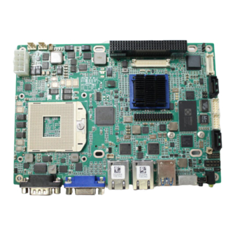
ADLINK Technology ReadyBoard 910 Reference Manual (64 pages)
P/N 50-1Z115-1000
Brand:
ADLINK Technology
| Category:
Motherboard
| Size: 3.19 MB
Table of Contents
Table of Contents
3
Chapter 1 About this Manual
7
Purpose of this Manual
7
References
7
Chapter 2 Product Overview
9
EPIC Architecture
9
Figure 2-1. Typical Readyboard and PC/104 Module Stack
9
Product Description
10
Figure 2-2. PCI-104 Modules Stacked on a Readyboard 910
10
Board Features
11
Block Diagram
14
Figure 2-3. Functional Block Diagram
14
Major Components (Ics)
15
Table 2-1. Major Component Descriptions and Functions
15
Figure 2-4. Component Locations
16
Header, Connector, and Socket Definitions
17
Table 2-2. Header, Connector, and Socket Descriptions
17
Figure 2-5. Header and Connector Pin Sequence
18
Figure 2-6. Header, Connector, and Socket Locations
19
Jumper Header Definitions
20
Figure 2-7. Jumper Header Locations (Top Side)
20
Table 2-3. Jumper Settings
20
Specifications
21
Power Specifications
21
Environmental Specifications
21
Table 2-4. Power Supply Requirements
21
Thermal/Cooling Requirements
22
Physical Specifications
22
Mechanical Specifications
23
Figure 2-8. Mechanical Overview (IO Panel)
23
Figure 2-9. Mechanical Overview (Top Side)
24
Chapter 3 Hardware
25
Overview
25
Cpu
26
Graphics
26
Memory
26
Interrupt Channel Assignments
27
Memory Map
28
I/O Address Map
28
Serial Interfaces
30
Figure 3-1. RS-485 Serial Port Implementation
30
Table 3-4. Serial Port 2 (CN8) Interface Pin Signals
31
USB Interfaces
32
Audio Interface
32
Video Interfaces
33
DVI
34
Table 3-8. DVI Pin Signal Descriptions (CN4)
34
LVDS Interface
35
EXT Interface
36
Miscellaneous
37
Real Time Clock (RTC)
37
External Battery
37
External Beeper/Buzzer Interface
37
Clear CMOS Switch
37
System Reset Switch
37
Temperature Monitoring
38
User GPIO Signals
38
Oops! Jumper (BIOS Recovery)
38
Figure 3-2. Oops! Jumper Connection
38
Serial Console
39
Serial Console Setup
39
System Management Bus (Smbus)
39
Figure 3-3. Hot Cable Jumper
39
Watchdog Timer
40
Power Interfaces
40
Power in
40
Power on
41
Power-On Button
41
Fan Interfaces
41
Power and Sleep States
42
Sleep States (ACPI)
42
Wake up Activities
44
Chapter 4 BIOS Setup
45
Introduction
45
Entering BIOS Setup (Local Video Display)
45
Entering BIOS Setup (Serial Port Console)
45
OEM Logo Screen (Splash)
46
Logo Image Requirements
46
BIOS Setup Menus
47
BIOS Main Setup Screen
47
Figure 4-1. BIOS Main Setup Screen
47
BIOS Advanced Setup Screen
48
Figure 4-2. BIOS Advanced Setup Screen
48
BIOS Chipset Setup Screen
52
Figure 4-3. BIOS Chipset Setup Screen
52
BIOS Boot Setup Screen
54
Figure 4-4. BIOS Boot Setup Screen
54
BIOS Security Setup Screen
55
Figure 4-5. BIOS Security Setup Screen
55
BIOS Save & Exit Setup Screen
56
Figure 4-6. BIOS Save & Exit Setup Screen
56
Appendix A Technical Support
59
Table A-1. Technical Support Contact Information
59
Index
61
Advertisement
Advertisement
Related Products
ADLINK Technology CoreModule 920
ADLINK Technology 96864-1
ADLINK Technology ReadyBoard 850
ADLINK Technology ReadyBoard 740
ADLINK Technology ReadyBoard 620
ADLINK Technology AmITX-AL-I
ADLINK Technology AmITX-BE-G
ADLINK Technology AmITX-BT-I
ADLINK Technology AmITX-CF-G
ADLINK Technology AmITX-HL-G
ADLINK Technology Categories
Computer Hardware
Motherboard
PCI Card
Control Unit
Controller
More ADLINK Technology Manuals
Login
Sign In
OR
Sign in with Facebook
Sign in with Google
Upload manual
Upload from disk
Upload from URL