Sign In
Upload
Manuals
Brands
ADLINK Technology Manuals
Computer Hardware
Q7-AL
ADLINK Technology Q7-AL Manuals
Manuals and User Guides for ADLINK Technology Q7-AL. We have
1
ADLINK Technology Q7-AL manual available for free PDF download: User Manual
ADLINK Technology Q7-AL User Manual (95 pages)
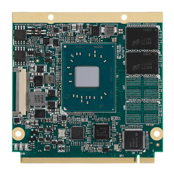
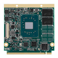
Qseven Computer On Module (COM) with Embedded Intel Atom, Pentium, and Celeron Processors
Brand:
ADLINK Technology
| Category:
Computer Hardware
| Size: 5 MB
Table of Contents
Table of Contents
3
Preface
4
List of Figures
5
1 Introduction
7
2 Specifications
9
Core System
9
Expansion Busses
9
Video
10
Audio
11
Lan
11
Multi I/O and Storage
12
Serial I/O on Module
13
SEMA Board Controller
13
Debug
14
Power Specifications
14
Power Consumption
14
Operating Temperatures
15
Environmental
15
Specification Compliance
15
Operating Systems
15
Functional Diagram
16
Figure 1: Q7-AL Functional Block Diagram
16
Mechanical Drawing
17
Figure 2: Q7-AL Mechanical Drawing
17
Q7-AL Heatspreaders
18
Figure 3: Q7-AL-HS1 Heat Spreader Mechanical Drawing
18
Figure 4: Q7-AL-HS2 Heat Spreader Mechanical Drawing
19
Figure 5: Q7-AL-HS4 Passive Heatsink Mechanical Drawing
20
Figure 6: Q7-AL-HS5 Passive Heatsink Mechanical Drawing
21
Q7-AL Top View and Bottom View
22
3 Pinouts and Signal Descriptions
23
Primary/Secondary Pin Definitions
23
Table 1: Q7-AL Primary/Secondary Pin Definitions
23
Signal Description Terminology
28
Qseven Signal Descriptions
29
4 Connector Pinouts on Module
39
Connector, Switch, and LED Locations
39
Q7-AL and the DB40 Debug Module
39
Figure 7: Q7-AL Connector, Switch and LED Locations
39
36-Pin MIPI-CSI2 Camera Connector
40
Figure 8: Q7-AL and the DB40 Debug Module
40
Table 2: 36-Pin MIPI-CSI Camera Connector Pin Definition on the Qseven Module
41
40-Pin Debug Connector
42
Table 3: 40-Pin Debug Connector Pin Definition on the Qseven Module
42
Status Leds
43
Figure 9: Q7-AL LED Locations
43
Table 4: LED Descriptions
44
BIOS Switch Settings
45
Figure 10: Q7-AL BIOS Switch Location
45
Table 5: BIOS Select and Mode Configuration Switch Settings
45
5 Smart Embedded Management Agent (SEMA)
47
Board Specific SEMA Functions
48
Table 6: SEMA Onboard Voltage Monitor
48
Table 7: SEMA BMC Status
48
Table 8: SEMA Exception Codes
49
Table 9: SEMA BMC Flags
49
6 System Resources
51
System Memory Map
51
Direct Memory Access Channels
51
I/O Map
51
Interrupt Request (IRQ) Lines
53
PCI Configuration Space Map
54
PCI Interrupt Routing Map
56
Smbus Address Table
56
7 BIOS Setup
57
Menu Structure
57
Main
58
Advanced
60
Chipset
70
Security
76
Boot
77
8 BIOS Checkpoints, Beep Codes
79
Status Code Ranges
80
Standard Status Codes
80
OEM-Reserved Checkpoint Ranges
87
9 Mechanical Information
89
Board-To-Board Connector
89
Thermal Solution
90
Mounting Requirements
93
Figure 11: Qseven Mounting Requirements
93
Safety Instructions
94
Getting Service
95
Advertisement
Advertisement
Related Products
ADLINK Technology Q7-BT
ADLINK Technology Intel Q7-EL
ADLINK Technology Q7-BASE
ADLINK Technology Qseven
ADLINK Technology 10GbE BASE-T
ADLINK Technology ACL -6128
ADLINK Technology ACL-8316/12
ADLINK Technology AMC-7000
ADLINK Technology AMD COM Express Express-VR7
ADLINK Technology AmITX-CF-I
ADLINK Technology Categories
Computer Hardware
Motherboard
PCI Card
Control Unit
Desktop
More ADLINK Technology Manuals
Login
Sign In
OR
Sign in with Facebook
Sign in with Google
Upload manual
Upload from disk
Upload from URL