Sign In
Upload
Manuals
Brands
ADLINK Technology Manuals
Computer Hardware
NuDAQ PCI-9222
ADLINK Technology NuDAQ PCI-9222 Manuals
Manuals and User Guides for ADLINK Technology NuDAQ PCI-9222. We have
1
ADLINK Technology NuDAQ PCI-9222 manual available for free PDF download: User Manual
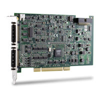
ADLINK Technology NuDAQ PCI-9222 User Manual (78 pages)
16-bit High-Performance DAQ Card with Programmable Function I/O
Brand:
ADLINK Technology
| Category:
Computer Hardware
| Size: 1 MB
Table of Contents
Table of Contents
7
List of Tables
9
1 Introduction
13
Features
14
Applications
14
Specifications
15
Unpacking Checklist
20
Software Support
20
Driver Support for Windows
21
Figure 1-1: ADLINK Software Support Overview
21
Figure 1-2: Daqpilot Main Interface
21
Figure 1-3: Daqmaster Device Manager
22
Figure 1-4: Legacy Software Support Overview
23
2 Hardware Information
25
Card Layout
25
Connector Pin Assignment
25
Figure 2-1: PCI-9222/PCI-9223 Layout
25
CN1 Pin Assignment
26
Table 2-1: CN1 Pin Assignment for PCI-9222
26
Table 2-2: CN1 Pin Assignment for PCI-9223
27
CN2 Pin Assignment
28
Table 2-3: CN2 Pin Assignment for PCI-9222/PCI-9223
28
CN1/CN2 Signal Descriptions
29
Table 2-4: CN1/CN2 Signal Description
29
SSI Connector Pin Assignment
30
Table 2-5: SSI Connector Pin Assignment
30
SSI Connector Signal Description
31
Table 2-6: SSI Connector Signal Description
31
Analog Input Signal Connection
32
Types of Signal Sources
32
Input Configurations
33
Figure 2-2: Floating Source and RSE Input Connections
33
Figure 2-3: Ground-Referenced Sources and NRSE Input Connections
34
Figure 2-4: Ground-Referenced Source and Differential Input
34
Figure 2-5: Floating Source and Differential Input
35
3 Installation
37
Before You Proceed
37
Installing the Card
37
Configuring the Card
38
Configuration
38
Troubleshooting
38
4 Operation Theory
39
Block Diagram
39
Figure 4-1: PCI-9222/PCI-9223 Block Diagram
39
A/D Conversion
40
Figure 4-2: PCI-9222/PCI-9223 AI Circuitry
40
Acquisition Mode (Software Polling)
41
AI Data Format
41
Software Conversion with Polling Data Transfer
41
Table 4-1: Bipolar Analog Input Range and Output Digital Code
41
Table 4-2: Bipolar Analog Input Range and Output Digital Code
41
Continuous Acquisition (Scanning) Mode
42
Figure 4-3: Continuous A/D Conversion Clock Source
42
Figure 4-4: Scan Timing
43
Figure 4-5: Post Trigger Without Retrigger
45
Trigger Modes
45
Figure 4-6: Post Trigger with Retrigger
46
Bus-Mastering DMA Data Transfer
47
Figure 4-7: Gated Trigger with Finite Scan Acquisition
47
Figure 4-8: Scatter-Gather DMA for Data Transfer
48
D/A Conversion
50
Bipolar Output Modes
50
Software Update
50
Waveform Generation
50
Table 4-3: Bipolar Output Codes
50
Figure 4-9: FIFO Data In/Out Structure
51
Figure 4-10: Waveform Generation for Three Channels Update
51
Table 4-4: Summary of Counters for Waveform Generation
52
Figure 4-11: Waveform Generation Clock Source Selection
52
Figure 4-12: Typical D/A Timing of Waveform Generation
53
Figure 4-13: Post-Trigger Generation
54
Figure 4-14: Delay-Trigger Generation
55
Figure 4-15: Post-Trigger with Retrigger Generation
56
Figure 4-16: Finite Iterative Waveform Generation with
57
Figure 4-17: Infinite Iterative Waveform Generation with
58
Programmable Function I/O
59
Ttl DI/Do
59
Table 4-5: TTL DIO Pins in CN1
59
General Purpose Timer/Counter
60
Basic Timer/Counter Functions
60
Table 4-6: Timer/Counter Mode Pins in CN1
60
General Purpose Timer/Counter Modes
61
Figure 4-18: Mode 1 Operation
61
Figure 4-19: Mode 2 Operation
62
Figure 4-20: Mode 3 Operation
63
Figure 4-21: Mode 4 Operation
63
Figure 4-22: Mode 5 Operation
64
Figure 4-23: Mode 6 Operation
64
Figure 4-24: Mode 7 Operation
65
Figure 4-25: Mode 8 Operation
65
Figure 4-26: Mode 9 Operation
66
Figure 4-27: Mode 10 Operation
66
Digital Waveform Acquisition and Generation
67
Figure 4-28: Digital Waveform Acquisition Operation
67
Figure 4-29: Digital Waveform Generation Operation
68
Isolation Encoder
69
Table 4-7: Encoder Pins in CN2
69
Figure 4-30: Encoder Isolation Input Module
69
Figure 4-31: Encoder Ogrx Input
70
Figure 4-32: CW/CCW Encoder Timing
70
Figure 4-33: X1 Encoder Mode
71
Figure 4-34: X2 Encoder Mode
71
Figure 4-35: X4 Encoder Mode
72
Figure 4-36: Phase Z
73
Trigger Sources
74
Software Trigger
74
External Digital Trigger
74
Figure 4-37: External Digital Trigger
74
5 Calibration
75
Loading Calibration Constants
75
Auto-Calibration
75
Saving Calibration Constants
76
Warranty Policy
77
Advertisement
Advertisement
Related Products
ADLINK Technology NuDAQ PCI-9223
ADLINK Technology PCI-9111
ADLINK Technology PCI-9118 DG
ADLINK Technology PCI-9118 HG
ADLINK Technology PCI-9118 HR
ADLINK Technology PCI-3488
ADLINK Technology PCIe-ACC100
ADLINK Technology PCIe-A100
ADLINK Technology PCI-PMC-7852/G
ADLINK Technology NuDAQ PCIe-9121
ADLINK Technology Categories
Computer Hardware
Motherboard
PCI Card
Control Unit
Desktop
More ADLINK Technology Manuals
Login
Sign In
OR
Sign in with Facebook
Sign in with Google
Upload manual
Upload from disk
Upload from URL