Sign In
Upload
Manuals
Brands
ADLINK Technology Manuals
Computer Hardware
MXE-5401
User Manuals: ADLINK Technology MXE-5401 Computer
Manuals and User Guides for ADLINK Technology MXE-5401 Computer. We have
1
ADLINK Technology MXE-5401 Computer manual available for free PDF download: User Manual
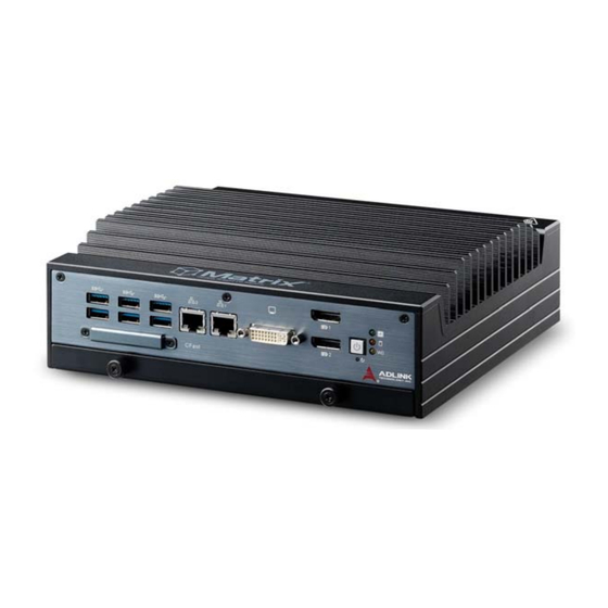
ADLINK Technology MXE-5401 User Manual (88 pages)
MXE-5400 Series Fanless Embedded Computer
Brand:
ADLINK Technology
| Category:
Computer Hardware
| Size: 4 MB
Table of Contents
Revision History
2
Preface
3
Table of Contents
5
List of Tables
9
List of Figures
11
1 Introduction
13
Overview
13
Features
14
Specifications
15
Unpacking Checklist
17
Figure 1-1: MXE-5400 Functional Block Diagram
17
Quick Start Guide
17
Mechanical Drawings
18
Figure 1-2: Top View
18
Figure 1-3: Front View
19
Figure 1-4: Rear View
19
Figure 1-5: (Left) Side View
19
Front Panel I/O Connectors
20
Power Button
20
Table 1-1: MXE-5400 Front Panel I/O Connector Legend
20
Figure 1-6: Front Panel I/O
20
LED Indicators
21
Reset Button
21
Table 1-2: LED Indicators
21
Dual Displayport Connector
22
Table 1-3: Displayport Pin Assignment
22
Multi-Display Option
23
DVI-I Connector
23
Table 1-4: Multi-Display Configuration
23
Table 1-5: DVI-I Connector Pin Assignment
24
Dual Gigabit Ethernet Ports
25
USB 3.0 Ports
26
Table 1-6: Gigabit Ethernet Port LED Function
26
Figure 1-7: Gigabit Ethernet Ports
26
Cfast Port
27
Rear Panel I/O Connectors
27
Figure 1-8: Rear Panel I/O
27
Table 1-7: MXE-5400 Rear Panel I/O Connector Legend
27
DB-62P COM Port and Digital I/O Connector
28
Figure 1-9: DB-62P COM Port
28
Figure 1-10: D-SUB 9P COM Connector
29
Table 1-8: DB-62P COM Port Pin Assignment
29
Table 1-10: Digital I/O Specifications
30
Table 1-9: D-SUB 9P COM Pin Assignment
30
Figure 1-11: D-SUB 26P Connector on Digital I/O Port
31
Figure 1-12: Isolated Digital Input Circuit
31
Isolated Digital Input Circuits
31
Table 1-11: D-SUB 26P Pin Assignment on Digital I/O Port
31
Figure 1-13: Isolated/Differential Digital Input Circuit
32
Figure 1-14: Isolated Digital Input Sample Application Circuit
32
Figure 1-15: Isolated Digital Output Circuits
33
Figure 1-16: Isolated Digital Output Sample Application Circuit
33
Isolated Digital Output Circuits
33
Internal I/O Connectors
34
Figure 1-17: Internal I/O
34
Table 1-12: MXE-5400 Internal I/O Legend
34
Clear CMOS Jumper
35
DC 5V and 3.3V Connectors for GPS Module
35
Figure 1-18: Clear CMOS Jumper Pin Settings
35
Table 1-13: Clear CMOS Jumper Pin Assignment
35
Figure 1-19: DC 5V and 3.3V Connectors Configuration
36
SATA Connectors (X2)
36
Table 1-14: DC 5V and 3.3V Connectors Pin Assignments
36
USIM Port
36
Figure 1-20: Mini-Pcie Connector Jumper Settings
37
Mini-Pcie Connectors
37
Extendable Power/Reset/Led
38
Figure 1-21: Extendable Power/Reset/Led Configuration
38
Table 1-15: Extendable Power/Reset/Led Connectors Pin Assignments
38
2 Getting Started
39
Installing Hard Disk Drives
39
Installing a Mini-Pcie Device
43
Internal USB Connector
45
Installing Cfast Card
46
COM Ports and DIO Device
48
Connecting DC Power
50
Wall-Mounting the MXE-5400
50
Cooling Considerations
53
3 Driver Installation
55
Installing the Chipset Driver
55
Installing the Graphics Driver
56
Installing the Ethernet Driver
56
Installing the Audio Driver
57
Installing the SEMA Utility, WDT and DI/O Drivers
57
A Appendix: Watchdog Timer (WDT)
59
DI/O Function Libraries
59
WDT with Api/Windows
59
Initwdt
59
Setwdt
60
DI/O with Api/Windows
62
Gpio_Init
62
Gpi_Read()
62
Gpo_Write()
63
Gpo_Read()
63
B Appendix: BIOS Setup
65
Main
66
BIOS Information
66
System Time/System Date
66
B.1 Main
66
Advanced
67
B.2 Advanced
67
CPU Configuration
68
Memory Configuration
70
Onboard Device Configuration
71
Advanced Power Management
73
Table B-1: Restore on Power Loss Settings
73
SATA Configuration
74
Serial Port Console Redirection
75
AMT Configuration
76
Intel® Rapid Start Technology
77
Trusted Computing Configuration
78
System Management (SEMA)
79
Chipset
80
B.3 Chipset
80
Boot
81
Boot Configuration
81
B.4 Boot
81
Boot Option Priorities
82
Security
82
Exit
83
B.6 Exit
83
Important Safety Instructions
85
Getting Service
87
Advertisement
Advertisement
Related Products
ADLINK Technology Matrix MXE-3000 Series
ADLINK Technology Matrix MXE-3002
ADLINK Technology MXM-P1000
ADLINK Technology MCM-100
ADLINK Technology MCM-102
ADLINK Technology MCM-216
ADLINK Technology MCM-218
ADLINK Technology MXM-AXe
ADLINK Technology MEC-AI7400SR
ADLINK Technology MXE-5600 Series
ADLINK Technology Categories
Computer Hardware
Motherboard
PCI Card
Control Unit
Desktop
More ADLINK Technology Manuals
Login
Sign In
OR
Sign in with Facebook
Sign in with Google
Upload manual
Upload from disk
Upload from URL