Sign In
Upload
Manuals
Brands
ADLINK Technology Manuals
Desktop
MVP-6143
ADLINK Technology MVP-6143 Manuals
Manuals and User Guides for ADLINK Technology MVP-6143. We have
1
ADLINK Technology MVP-6143 manual available for free PDF download: User Manual
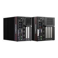
ADLINK Technology MVP-6143 User Manual (107 pages)
Processor-Based Fanless Expandable Computer
Brand:
ADLINK Technology
| Category:
Desktop
| Size: 10 MB
Table of Contents
Table of Contents
5
List of Tables
7
List of Figures
9
Introduction
11
Overview
11
Features
11
Packing List
12
Optional Accessories
12
Specifications
13
Mvp-612X/Mvp-614X/Mvp-612A/Mvp-614A
13
Mvp-6121/Mvp-6141/Mvp-6122/Mvp-6142
15
Mvp-6123/Mvp-6143/Mvp-6124/Mvp-6144
17
MVP-6100 Functional Block Diagram
19
Display Options
20
Table 2-1: Max. Available Resolution Display Configuration
20
Mechanical Dimensions
21
Figure 2-1: MVP-6120 Front View
21
Figure 2-2: MVP-6140 Front View
22
Figure 2-3: MVP-6120/6140 Left Side View
23
Figure 2-4: MVP-6120/6140 Right Side View
24
Figure 2-5: MVP-6120/6140 Top View (Incl. Wall-Mount Brackets)
25
System Layout
27
Front Panel
27
Table 3-1: Front Panel I/O Legend
27
Figure 3-1: Front Panel I/O
27
Table 3-2: LED Indicators
28
Table 3-3: Displayport Pin Definition
29
Table 3-4: Applicable Cable Types
29
Figure 3-2: Displayport Connector Pin Definition
29
Table 3-5: Digital Input/Output Connector Pin Definition
30
Figure 3-3: Digital I/O Connector Pin Definition
30
Figure 3-4: Digital Input Circuit
31
Figure 3-5: Digital Output Circuit
31
Table 3-6: DVI-D Connector Pin Definition
32
Figure 3-6: DVI-D Connector Pin Definition
32
Table 3-7: VGA Connector Pin Definition
33
Figure 3-7: VGA Connector Pin Definition
33
Table 3-8: Ethernet Port Pin Definition
35
Table 3-9: Active/Link LED Indicators
35
Table 3-10: Speed LED Indicators
35
Figure 3-8: Ethernet Port and Leds
35
Table 3-11: DC Power Input Pin Definition
36
Figure 3-9: DC Power Input
36
Table 3-12: D-Sub 9-Pin Signal Function of COM Ports
37
Figure 3-10: COM Port Pin Definition
37
Figure 3-11: Cfast Host Slot
38
Internal I/O Connectors
39
Figure 3-12: Mainboard Connectors
39
Table 3-13: Mainboard Connector Legend
40
Table 3-14: 2-Slot Backplane Board Connector Legend
41
Figure 3-13: 2-Slot Backplane Board Connectors
41
Table 3-15: 4-Slot Backplane Board Connector Legend
42
Figure 3-14: 4-Slot Backplane Board Connectors
42
Table 3-16: GPS Module Power Header Pin Definition
43
Figure 3-15: GPS Module Power Header Pin Definition
43
Table 3-17: 12V Fan Connector Pin Definition
44
Figure 3-16: 12V Fan Connector Pin Definition
44
Figure 3-17: Clear CMOS Jumper Setting
44
Table 3-18: PWR/RESET Header Pin Definition
45
Table 3-19: 12V Power Pin Definition
45
Figure 3-18: PWR/RESET Header Pin Definition
45
Figure 3-19: 12V Power Pin Definition
45
Getting Started
47
Attach DC Power Connector
47
Mounting the MVP-6100
48
Driver Installation
50
A Appendix: Power Consumption
51
Power Consumption Reference
51
Table A-1: Power Consumption
51
B Appendix: BIOS Setup
53
Main
54
Advanced
56
Chipset
73
Security
87
Boot
89
Save & Exit
91
C Appendix: Watchdog Timer (WDT) Function Library
93
WDT with Api/Windows
93
WDT with Dos/Linux
96
D Appendix: Digital Input/Output Function Library
99
Important Safety Instructions
101
Consignes de Sécurité Importante
103
Getting Service
107
Advertisement
Advertisement
Related Products
ADLINK Technology MVP-6100
ADLINK Technology MVP-6120
ADLINK Technology MVP-6140
ADLINK Technology MVP-6123
ADLINK Technology MVP-6124
ADLINK Technology MVP-6144
ADLINK Technology MVP-6000 Series
ADLINK Technology MVP-6003
ADLINK Technology Value MVP-6220
ADLINK Technology Value MVP-6240
ADLINK Technology Categories
Computer Hardware
Motherboard
PCI Card
Control Unit
Desktop
More ADLINK Technology Manuals
Login
Sign In
OR
Sign in with Facebook
Sign in with Google
Upload manual
Upload from disk
Upload from URL