Sign In
Upload
Manuals
Brands
ADLINK Technology Manuals
Motherboard
cPCI-3920B
ADLINK Technology cPCI-3920B Manuals
Manuals and User Guides for ADLINK Technology cPCI-3920B. We have
1
ADLINK Technology cPCI-3920B manual available for free PDF download: User Manual
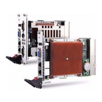
ADLINK Technology cPCI-3920B User Manual (106 pages)
cPCI-3920 Series 3U CompactPCI Single Board Computer with Intel Core 2 Duo, Core Duo, Celeron M Processor
Brand:
ADLINK Technology
| Category:
Motherboard
| Size: 1.45 MB
Table of Contents
Revision History
2
Table of Contents
5
List of Tables
9
1 Overview
11
Introduction
11
Features
12
Block Diagram
13
Figure 1-1: Cpci-3920 Block Diagram
13
Product List
14
Sbc
14
Rear Transition Module
14
Accessories
14
Package Contents
15
CPU Module
15
Rear Transition Module
15
2 Specifications
17
CPU, Memory, and Chipset
17
Interfaces
17
Software
19
Mechanical
19
Environmental
19
I/O Connectivity Table
20
Table 2-1: I/O Connectivity
20
Power Consumption
21
Table 2-2: Power Consumption of Core™ 2 Duo LV (L7400)
21
Table 2-3: Power Consumption of Core™ 2 Duo LV (U2500)
22
Table 2-4: Power Consumption of Celeron M LV(423)
23
Mechanical Dimensions
24
Cpci-3920A
24
Cpci-3920B
24
Figure 2-1: Cpci-3920 Mechanical Dimensions
24
Cpci-R3920
25
Cpci-R3920T
25
Figure 2-2: Cpci-R3920 Mechanical Dimensions
25
Board Layout
26
Cpci-3920 Board Layout
26
Figure 2-3: Cpci-3920 Board Layout
26
Figure 2-4: Cpci-3920A Assembly and Front Panel
27
Figure 2-5: DB-3920L2 Daughter Board Layout
28
Figure 2-6: Cpci-3920B Assembly and Front Panel
29
Figure 2-7: Cpci-R3920(T) Board Layout and Front Panel
30
3 Functional Description
31
CPU, Memory and Chipset
31
CPU: Intel® Core™ Duo and Intel® Core™2 Duo
31
Intel® Celeron® M
32
Supported Processors, Maximum Power Dissipation
33
Table 3-1: Supported Processors, Power Dissipation
33
Memory
34
Intel® 3100 Chipset Overview
34
Figure 3-1: Intel® 3100 Chipset Block Diagram
34
Volari™ Z11 Graphics Controller
36
Peripherals
38
Timer
38
Watchdog Timer
38
Battery
39
Reset
39
Smbus Devices
40
Thermal Management/ System Monitoring
40
Table 3-2: Smbus Devices and Addresses
40
FWH Flash Memory
41
LED Functions
41
Table 3-3: LED Function Descriptions
41
Board Interfaces
42
USB Interfaces
42
Table 3-4: Front Panel USB Connector Pin Definition
42
Table 3-5: Onboard USB Connector Pin Definition
43
Graphics Controller
45
Dual Gigabit Ethernet
46
Table 3-6: VGA Connector CN3 Pin Definition
46
Table 3-7: Gigabit Connector CN7/CN8 Pin Definitions
47
Board-To-Board Connector
48
Table 3-8: Ethernet LED Status Definitions
48
Table 3-9: Board-To-Board Connector Pin Definition
49
Keyboard/ Mouse Interface
50
Table 3-10: PS/2 Keyboard/Mouse Connector Pin Definition
50
Universal Serial Ports
51
Table 3-11: COM3 Serial Port Connector Pin Definition
51
Table 3-12: COM4 Serial Port Connector Pin Definition
51
Table 3-13: COM4 Mode Switch Settings
52
Serial ATA Interfaces
53
Table 3-14: SATA0 Connector Pin Definition
54
Compactpci Bus Interfaces
55
Table 3-15: Compactpci J1 Pin Assignment
56
Table 3-16: Compactpci J2 Pin Assignment
58
Board Interfaces on RTM
59
Gigabit Ethernet Interfaces
59
Table 3-17: RTM USB Connector Pin Definitions
59
COM1 and COM2 Interfaces
60
Table 3-18: RTM Gigabit Connector Pin Definitions
60
Serial ATA Interfaces - SATA1-3
61
Table 3-19: COM1 Serial Port Connector Pin Definition
61
Table 3-20: COM2 Serial Port Connector Pin Definition
61
SATA1-3 Connectors CN2-R, CN4-R and CN5-R
62
Rear I/O Interfaces on Compactpci Connector Rj2
62
Table 3-21: SATA1-3 Connectors Pin Definition
62
Table 3-22: Compactpci Rj2 Pin Assignment
64
4 Getting Started
65
Safety Requirements
65
Installing the Hard Disk Drive
66
Installing the Cpci-3920 to the Chassis
67
RTM (Cpci-R3920) Installation
67
Hot Swap Procedures
68
5 Driver Installation
69
6 Watchdog Timer
71
WDT Overview
71
Figure 6-1: Cpci-3920 Watchdog Timer Architecture
71
Using the Watchdog Timer in an Application
72
7 BIOS Setup Utility
77
Starting the BIOS
77
Setup Menu
78
Navigation
78
Hotkey Descriptions
80
Main Setup
81
System Time/System Date
81
Advanced BIOS Setup
82
CPU Configuration
83
IDE Configuration
84
AHCI Configuration
86
USB Configuration
86
Hardware Health Configuration
89
Pci/Pnp Setup
90
Irq
90
DMA Channel
90
Boot Setup
91
Boot Setting Configuration
91
Boot Device Priority
93
Removable Drives
94
Security Setup
95
Password Support
95
Supervisor Password
96
User Password
96
Change Supervisor Password
96
Change User Password
96
Clear User Password
96
Change User Password
97
Chipset Setup
98
South Bridge Configuration
98
Exit Menu
100
Save Changes and Exit
100
Discard Changes and Exit
101
Discard Changes
101
Load Optimal Defaults
101
Load Failsafe Defaults
101
Important Safety Instructions
103
Warranty Policy
105
Advertisement
Advertisement
Related Products
ADLINK Technology cPCI-3920 Series
ADLINK Technology cPCI-3915B
ADLINK Technology cPCI-3915A
ADLINK Technology cPCI-3920A
ADLINK Technology cPCI-6810A/P9
ADLINK Technology cPCI-6810B/P9
ADLINK Technology cPCI-6820B/P9
ADLINK Technology cPCI-6810A/1G
ADLINK Technology cPCI-6820A/1G
ADLINK Technology cPCI-6910/DCX16/M2G
ADLINK Technology Categories
Computer Hardware
Motherboard
PCI Card
Control Unit
Controller
More ADLINK Technology Manuals
Login
Sign In
OR
Sign in with Facebook
Sign in with Google
Upload manual
Upload from disk
Upload from URL