Sign In
Upload
Manuals
Brands
ADLINK Technology Manuals
Control Unit
AVA-5500 Series
ADLINK Technology AVA-5500 Series Manuals
Manuals and User Guides for ADLINK Technology AVA-5500 Series. We have
1
ADLINK Technology AVA-5500 Series manual available for free PDF download: User Manual
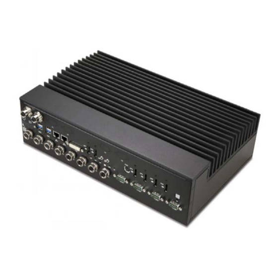
ADLINK Technology AVA-5500 Series User Manual (79 pages)
AI-Enabled Video Analytics Platform
Brand:
ADLINK Technology
| Category:
Control Unit
| Size: 3 MB
Table of Contents
Preface
3
Table of Contents
5
List of Figures
9
List of Tables
11
1 Introduction
13
Overview
13
Features
14
Package Contents
15
2 System Description
17
AVA-5500/5510 Specifications
17
Table 2-1: AVA-5500/5510 Specifications
17
Displayport Feature Support
20
Table 2-2: Displayport Feature Support
20
Block Diagram
21
Figure 2-1: AVA-5500 Block Diagram
21
Mechanical Dimensions
22
Figure 2-2: AVA-5500/5520 Dimensions
22
Figure 2-3: AVA-5510 Dimensions
23
Mechanical Layout
24
Figure 2-4: AVA-5500 Series Front Layout
24
Figure 2-5: AVA-5500/5200 Rear I/O Layout
25
Figure 2-6: AVA-5510 Rear I/O Layout
25
Power Specifications
26
Power Consumption
26
Table 2-3: AVA-5500/5510 Power Consumption
26
System Power Features
27
Table 2-4: AVA-5200 Power Consumption
27
Mini Pcie CAN Bus Module (Optional)
28
3 Getting Started
29
Removing the Bottom Cover
29
Installing Wi-Fi or Cellular Modules (Optional)
30
Installing a M.2 2280 SATA Module (Optional)
31
Installing Micro-USIM Cards (Optional)
32
Mounting
33
Cfast Card Installation
34
SATA Drive Installation
35
Connections
36
Starting up the System
38
4 Interfaces
39
Pin Definitions
39
Table 4-1: Gbe M12 A-Code Pin Definition
39
Table 4-2: Gbe M12 X-Code Pin Definition
39
Table 4-3: USB 3.0 Pin Definition
40
Table 4-4: COM Port Pin Definition
40
Table 4-5: RJ-45 Gbe Pin Definitions
41
Table 4-6: LAN LED Status Definitions
41
Table 4-7: DVI-I Connector Pin Definition
42
Table 4-8: Displayport Pin Definition
43
Table 4-9: PS/2 Keyboard/Mouse Pin Definition
43
Table 4-10: DC Power Input Pin Definition
43
Table 4-11: USB 2.0 M12 Connector Pin Definition
44
Table 4-12: CAN Bus Male DB9 Connector Pin Definition
44
Table 4-13: DIO DB9 Connector Pin Definition
45
Table 4-14: Mini PCI Express Connector Pin Definition
46
Table 4-15: M.2 Connector Pin Definition
48
Status Leds
49
Table 4-16: Status LED Definitions
49
Power Button
50
Reset Button
50
5 BIOS Setup
51
Introduction
51
Entering BIOS Setup
51
Main Setup
55
BIOS Information
55
System Information
56
System Time/System Date
56
Board Information
57
Advanced Menu
58
CPU Configuration
59
Graphics Configuration
61
Power Management
61
System Management
62
Thermal Management
64
Watchdog Timer
64
CSM Configuration
65
Super IO Configuration
66
Serial Port X Configuration
66
Serial Console Redirection
67
Miscellaneous
69
Network Stack Configuration
71
Trusted Computing
71
Intelethernet Connection (2) I210-LM
72
Security Menu
73
Secure Boot
73
Boot Menu
74
Save & Exit Menu
75
BIOS Beep Codes
75
Important Safety Instructions
77
Getting Service
79
Advertisement
Advertisement
Related Products
ADLINK Technology AVA-5510
ADLINK Technology AVA-5520
ADLINK Technology ADM-TJ30
ADLINK Technology AVA-3510
ADLINK Technology ACL -6128
ADLINK Technology ACL-7122
ADLINK Technology AmITX-SL-G
ADLINK Technology AmITX-RZ-G
ADLINK Technology NuDAQ ACL-8454
ADLINK Technology NuDAQ ACL-8454/12
ADLINK Technology Categories
Computer Hardware
Motherboard
PCI Card
Control Unit
Desktop
More ADLINK Technology Manuals
Login
Sign In
OR
Sign in with Facebook
Sign in with Google
Upload manual
Upload from disk
Upload from URL