Sign In
Upload
Manuals
Brands
Actis Manuals
Single board computers
VSBC-6872 Series
Actis VSBC-6872 Series Board Computer Manuals
Manuals and User Guides for Actis VSBC-6872 Series Board Computer. We have
1
Actis VSBC-6872 Series Board Computer manual available for free PDF download: User Manual
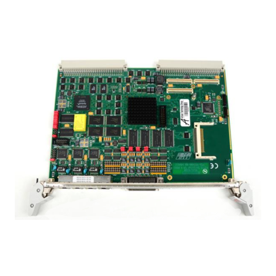
Actis VSBC-6872 Series User Manual (105 pages)
VMEbus Single Board Computer with Freescale MPC8270 processor
Brand:
Actis
| Category:
Single board computers
| Size: 5 MB
Table of Contents
Table of Contents
6
Figure 1 - VSBC-6872 Photograph
12
1 Introduction
14
Features
15
VSBC-6872 Block Diagram
16
Figure 2 - Block Diagram
16
Component Location
17
Figure 3 - Component Location - Top Assembly
17
2 Getting Started
18
Unpacking Instructions
18
Hardware Configuration
18
Base Board Configuration
18
Expansion Module Installation
18
Board Installation
18
Ecmon Monitor
19
Table 1 - Console Port Setting
19
3 Functional Description
20
Freescale MPC8270 Processor
20
Figure 4 - Freescale MPC8270 Block Diagram
20
SDRAM Controller
21
Table 2 - SDRAM Device Organization
21
Table 3 - SDRAM Initialization
21
Memory Management Unit
22
External Bus Controller
22
FLASH Memory
23
SRAM Memory
23
Table 4 - MPC8270 Reset Word
23
Real Time Clock
24
Figure 5 - RTC Snaphat Battery
24
Compactflash Card Interface
25
Table 5 - UPM Initialization for Compactflash
25
Fast Ethernet Communication Ports
26
SCC Multi-Protocol Serial Ports
26
Table 6 - Fast Ethernet Assignment
26
Figure 6 - SCC Block Diagram
27
Figure 7 - SCC Resistor Networks Location
27
Table 7 - SCC RS-485 Removable Resistor Networks
27
Interrupt Controller
28
Figure 8 - MPC8270 Interrupt Controller
28
Direct Memory Access Controller
29
I 2 C Serial Interface Bus
29
Figure 9 - DMA Block Diagram
29
VPD EEPROM (Vital Product Data)
30
Table 8 - VPD EEPROM Address
30
Table 9 - VPD Serial EEPROM Structure
30
Table 10 - VPD Options Field
30
MPC8270 PCI Bus
31
PMC Expansion Slot
31
Dual S-ATA Controller
31
Table 11 - PCI Bus Devices
31
Table 12 - PMC-P4 to VME-P2 Mapping
31
Vmebus Interface
32
60X-To-VME Bridge
32
Figure 10 - 60X-To-VME Bridge Block Diagram
32
Table 13 - UPM Initialization for Bridge Access
32
Vmebus Master
33
Vmebus Slave
33
Table 14 - VME Master Addressing Space Mapping
33
Table 15 - Bridge Registers Accessible from Vmebus
34
Table 16 - A24 Slave Memory Map
34
Figure 11 - VME Slave Window Defined by VSBA24
35
Figure 12 - VME Slave Window Defined by XSAV24
35
Vmebus Requester
36
Vmebus Interrupter
36
Vmebus Interrupt Handler
36
Vmebus Mailbox
36
Vmebus System Controller
37
Bridge DMA Controller
37
4 Bridge Registers
38
Table 17 - Bridge Registers List
38
5 Board Resources
58
Peripheral Chip Select
58
Memory Map
58
Table 18 - Chip Select Assignment
58
Table 19 - Memory Map
58
Interrupt Sources
59
Table 20 - Interrupt Sources
59
Table 21 - FCC Interrupt
59
Multiplexed General Purpose I/O Ports
60
Table 22 - GPIO Port a & B Controller Setting
60
Table 23 - GPIO Port C & D Controller Setting
61
6 Technical Characteristics
62
7 Hardware Description
64
Front Panel Connectors
64
Fast Ethernet Port FCC1
64
Figure 13 - Front Panel Connectors
64
Figure 14 - Fast Ethernet Port Connector
64
Table 24 - Fast Ethernet Connector Assignment
64
Table 25 - Network Status Leds
64
Console Port
65
Figure 15 - Console Port Connector
65
Table 26 - Console Port Pin Assignment
65
Table 27 - User Leds
65
Multi-Protocol Serial Ports SCC1
66
Figure 16 - Serial Port Connector
66
Table 28 - Serial Port Pin Assignment
66
Board Jumpers
68
Figure 17 - Board Jumpers
68
Table 29 - Board Jumper Configuration
68
Serial Communication Port Jumpers
69
Figure 18 - Serial Port Jumpers
69
Table 30 - Serial Port Jumper Location
69
Table 31 - Serial Port Jumper Configuration
69
IEEE1149.1 Test Access Port, P11 Connector
70
SPI/SMC2/I2C Connector
70
Figure 19 - Test Access Port Connector
70
Table 32 - IEEE1149.1 Connector Pin Assignment
70
Table 33 - SPI/SMC2/I2C Connector Pin Assignment
70
S-ATA Ports
71
Compactflash Connector
71
Figure 20 - S-ATA Connector Description
71
Table 34 - S-ATA Connector Pin Assignment
71
Table 35 - Compactflash Connector Pin Assignment
71
Vmebus P1 Connector
72
Table 36 - Vmebus P1 Connector Pin Assignment
72
Vmebus P2 Connector
73
Table 37 - Vmebus P2 Connector Pin Assignment
73
PCI Mezzanine Card (PMC)
74
Installing a PMC
74
Figure 21 - PMC Module Installation
74
PMC Interface, J11 Connector
75
Table 38 - J11 Connector Pin Assignment
75
PMC Interface, J12 Connector
76
Table 39 - J12 Connector Pin Assignment
76
PMC Interface, J14 Connector
77
Table 40 - J14 Connector Pin Assignment
77
8 Software Description
78
Ecmon Commands
78
Command Line and Syntax Rules
78
Command Descriptions
79
Table 41 - Ecmon Command Line Editing Shortcut Keys
79
Table 42 - Ecmon Command Overview
79
9 Web Resources
96
10 Ordering Information
98
11 Sales Department
100
12 Technical Support
100
Hardware and Software Assistance
100
13 OEM Warranty
102
RMA Request
102
14 Index
104
Advertisement
Advertisement
Related Products
Actis VSBC-6862
Actis Categories
Tablet
Motherboard
Control Unit
Car Navigation system
Single board computers
More Actis Manuals
Login
Sign In
OR
Sign in with Facebook
Sign in with Google
Upload manual
Upload from disk
Upload from URL