Sign In
Upload
Manuals
Brands
Actia Manuals
Measuring Instruments
Multi-Diag Scope
Actia Multi-Diag Scope Manuals
Manuals and User Guides for Actia Multi-Diag Scope. We have
1
Actia Multi-Diag Scope manual available for free PDF download: User Manual
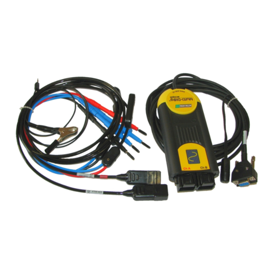
Actia Multi-Diag Scope User Manual (84 pages)
Brand:
Actia
| Category:
Measuring Instruments
| Size: 10 MB
Table of Contents
Table of Contents
2
Contents
4
Introduction
4
Safety Precautions
4
Ambient Conditions
4
Important Warning
4
Waste Disposal
5
Pc Requirements
5
Multi-Diag Scope Connection with Pc
5
Variants Power Supply of Multi-Diag Scope
6
Software Installation
7
Description of Installation CD and Its Running
7
Installation of Multi-Diag Scope Program
7
Program Configuration
7
Program Auto Update
8
Auto Update Indication on the Screen
8
Auto Update Indication on Multi-Diag Scope
8
Installation of a Found New Device (Hardware - Hw)
8
Installation of Atal Devices - General
8
Installation of the Usb-Rs 232 Converter
9
Installation of Drivers for the Usb-Rs 232 Converter
9
Adapter Usb-Rs 232 Final Installation
10
Technical Specifications
11
Oscilloscope
11
Multimetre
11
Program Multi-Diag Scope Start up
11
Error Message When Multi-Diag Scope Is Disconnected
12
Information about Software
13
Closing the Multi-Diag Scope Program
13
Control of Individual Functions and Setting of Oscilloscope Parameters
13
Conditions for Maximizing the Oscilloscope Window + Recommendation
13
Oscilloscope
14
Basic Screen
14
Showing/Hiding (Minimizing) the Control Panel
16
Description of Individual Parts
18
Description of Record Control and Setting
19
Description of the Control and Setting of a (B) Channel Parameters
20
Switchover of Connectors on the Channel B
20
Description of the Control and Setting of Time Base
21
Description of the Invert Control Function
21
Cursor Measurements
23
Description of the Function of Other Control Buttons
24
Control of Oscilloscope Parameters by the Mouse or Pointer in the Case of Touch Screen
25
Saving Waveforms
26
Opening Waveforms
27
Removal of the Stored Waveforms from the Screen Only
29
Printing of Displayed Waveforms
30
Oscilloscope User Setup Saving / Loading
31
User Setup Storage Options
31
Description of Control Buttons
34
Description of Selected Functions
34
Example of Using the Mode for Opening both Channels (Two-Pole Coil)
35
Error Messages
37
Voltmeter
37
Amperemeter
38
Current Probe - 5/50 a
39
Current Probe - 500 a
39
Current Probe Offset Zeroing
39
Ohmmeter
40
Probe Contact Resistance Zeroing
41
Resistance Measuring
41
Conductivity Test
42
Diode Measurement
42
Measurement on the Hv Coil - Secondary Winding (Since Sw Version - 11.0)
43
Hv Sensor N (At111 4018) + Hv Reference Cable (at 111 4056)
43
Hv Sensor C1 (At111 4017) + Hv Reference Cable (at 111 4056)
44
Measurement of Spark Voltage on the Reference High-Voltage
44
Measurement on the Hv Coil - Secondary Winding with Touch Hv Sensor
44
Signalling that Saturation Areas at the Input Have Been Reached
45
Universal Interconnection Kit
46
Print Queue
46
Using the Print Queue
46
Print Queue Preview
47
Chap. II - Multi-Diag Motortester
49
Introduction
49
Multi-Diag Scope and Motortester Connecting Procedure
49
Motortester Program Initialization
49
Error Message When Multi-Diag Scope Is Disconnected
50
Spark Ignition Engine Measurement
50
Advance Meter
51
Stroboscope
51
Voltage and Current Measuring
53
Note *) Direct-Current Core Magnetization Compensation
53
Measurement on the Hv Coil - Primary Winding
54
Primary Winding Voltage
55
Dwell Angle Measurement
55
Measurement on the Hv Coil - Secondary Winding
56
Types of High-Voltage Sensor and Their Use in Motortester
56
Hv Sensor N (At111 4018)
56
Hv Sensor (At111 4007)
57
Hv Measurement Synchronization
57
Probe Connection for One Cylinder Measurement
58
Probe Connection for All Cylinder Measurement
58
Measurement of Spark Voltage on the Reference High-Voltage
60
Single Cylinder Measurement
60
Note for Fig. 137 and Fig. 138 (Account of Buttons on / Off)
60
All Cylinders Measurement
61
Note for Fig. 140 (Account of Button Sync)
62
Connection of Hv Sensor C4
62
Double Coil Measurement
62
Manual Mode
62
Auto Mode
63
Selected Cylinder Measurement
64
Oil Temperature Measurement
65
Frequency Measuring Oscilloscope
66
Speed Engine Measuring Oscilloscope
66
Diesel Engine Measurement
67
Preinjection Meter
67
Voltage and Current Measurement
68
Pressure Sensor Signal
68
Thermometer
68
Oscilloscope
69
Speed Measuring Oscilloscope
69
Engine and Sensor Parameter Setting (Motortester Default Setup)
69
Description of Buttons in Motortester Setup - Param Menu
70
Edit (Setup) Buttons
70
Confirm (Delete) Buttons
71
Chap. III - Special Tests
72
Introduction
72
Special Tests Program Initialization
72
Description of Tests
72
List All Available Tests
72
Help - Sensor Connection
73
View of Motortester
73
Main Help Screen
73
Switchover to Another Application
75
Chap. IV - Record Analyzer
76
Introduction
76
Record Analyzer Program Initialization
76
Record Starting
76
Alternatives of Course Scanning
76
Continuous Sampling
76
Oscilloscope Time Basis: 1 Ms - 50 Ms
77
Oscilloscope Time Basis: 100 Ms - 2.5 Seconds
77
Discontinuous Sampling
78
Oscilloscope Time Basis: Less than 1 Ms
78
Description of Record Analyzer Program Screen
80
Screen with Cursors off
80
Screen with Cursors on
82
Cursor Description (Cursor Measuring)
84
If the Cursors Are Beyond the Screen
84
Advertisement
Advertisement
Related Products
Actia BOP xD
Actia Categories
Service Equipment
Automobile Accessories
Media Player
Measuring Instruments
Diagnostic Equipment
More Actia Manuals
Login
Sign In
OR
Sign in with Facebook
Sign in with Google
Upload manual
Upload from disk
Upload from URL