Sign In
Upload
Manuals
Brands
ABB Manuals
Controller
Galaxy Millennium J2011002
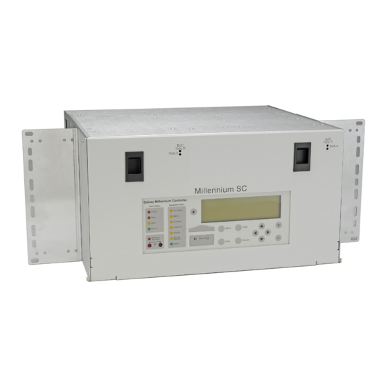
ABB Galaxy Millennium J2011002 Controller Manuals
Manuals and User Guides for ABB Galaxy Millennium J2011002 Controller. We have
1
ABB Galaxy Millennium J2011002 Controller manual available for free PDF download: Product Manual
ABB Galaxy Millennium J2011002 Product Manual (206 pages)
SC Controller
Brand:
ABB
| Category:
Controller
| Size: 7.87 MB
Table of Contents
Table of Contents
3
List of Figures
5
List of Tables
7
Introduction
10
Figure 1 MSC Chassis
11
Product Description
12
Overview
12
Figure 2 MSC Controller Front
12
Figure 3 Controller Arrangements
13
Figure 4 BJC Card Slots
14
Feature Summary
15
Standard System Features
15
Table 1 MSC Standard System Features
15
Front Panel User Interface
16
Figure 5 Front Panel
16
Local Serial Access
17
Remote Access
17
Table 2 Front Panel User Interface
17
Battery Management
18
Integrated Monitoring Inputs
19
Integrated Outputs
19
Hardware
20
Chassis
20
Figure 6 Controller Dimensions
20
Controller Cards
21
Figure 7 Card Locations
21
Figure 8 MCR1B/2B Circuit Card
22
Figure 9 MSCB_FB Fuse Card
22
Figure 10 Backplane
23
Figure 11 Modem BSM6
23
Figure 12 Alarm Termination Card BSL3_MSC
24
Figure 13 Rectifier Interface Card
24
Supporting Documents
25
Figure 14 Remote Interface Module (RIM)
25
Table 3 Supporting Documents
25
Front Panel
26
Default Display
26
Figure 15 Default Display
26
Lcd
27
Leds
27
Figure 16 Front Panel
27
Push-Button Keys
28
Test Jacks
28
Serial (PC) Port
28
Table 4 Push-Button Key Functionality
28
Alarm Buzzer
29
Contrast Adjust
29
Display Menus
30
Configuration Menus
30
Figure 17 Configuration Menus 1 of 2
30
Figure 18 Configuration Menus 2 of 2
31
Control and Operations Menus
32
Figure 19 Control and Operations Menus
32
History Menus
33
Statistics Menus
33
Figure 20 History Menus
33
Figure 21 Statistics Menus
33
Status Menus
34
Figure 22 Status Menus 1 of 2
34
Figure 23 Status Menus 2 of 2
35
Installation
36
Preparation
36
Safety and Precautions
36
Installation Materials
36
Plan Rectifier Interface Cards First ID Settings
36
Figure 24 RIC ID Setting
37
Table 5 Rectifier Interface Cards First ID Settings
38
Plan Wiring Transfer from Existing Controller
39
Prepare Galaxy SC Configuration File for MSC Use
40
Record Customer Specified Minimum Configuration
40
Remove Existing Controller
41
Galaxy SC Controller Removal
42
Figure 25 Galaxy SC Controller - Front
42
Figure 26 Galaxy SC Controller - Rear
42
Table 6 Galaxy SC Basic Controller (BJA) HVSD DIP Switch Settings
43
Table 7 Galaxy SC Basic Controller (BJB) DIP Switch Settings
44
Table 8 Galaxy SC Intelligent Controller (BJH) DIP Switch Settings
44
Table 9 Galaxy SC Alarm Threshold Settings
45
Table 10 Galaxy SC Plant Shunt Settings
45
Table 11 Galaxy SC Low Voltage Disconnects Settings
46
Table 12 Galaxy SC Slope Thermal Compensation Settings
46
Figure 27 LVLD Contactor EBV Card SW300
47
Table 13 Galaxy SC Rectifier Setpoints
47
Figure 28 LVBD Contactor Control BJN Card SW300
48
Table 14 Galaxy SC High Voltage Shutdown Setting -48V
49
Table 15 Galaxy SC High Voltage Shutdown Setting -+/-24V
51
Figure 29 Galaxy SC Rectifier Fuses
55
Figure 30 Galaxy SC TB2 and TB3
57
Figure 31 Galaxy SC TB1 Plant Connections
58
Figure 32 Galaxy SC Controller Fuses
58
MCS Controller Removal
60
Figure 33 MCS Alarm Circuit
60
Figure 34 MCS TB1 Alarm Connections
62
Figure 35 MCS Auxiliary Board (CP2)
64
Table 16 MCS DIP Switch Settings
64
Table 17 MCS-BD and LV2 Alarm Settings - S1
65
Table 18 MCS High Voltage Shutdown / Float - S2
66
Table 19 MCS High Voltage Shutdown / Equalize - S3
67
Other Controller Removal
68
Table 20 Other Controller DIP Switch Settings
68
Table 21 Other Controller Alarm Threshold Settings
69
Table 22 Other Controller Plant Shunt Settings
69
Table 23 Other Controller Low Voltage Disconnect Settings
69
Table 24 Other Controller Slope Thermal Compensation Settings
70
Table 25 Other Controller Rectifier Float Setpoints
70
Install Controller
75
Mount the MSC
75
Figure 36 MSC
75
Remove Controller Fuses
76
Figure 37 Fuse Card
76
Install Circuit Cards
77
Figure 38 Cards Front
77
Figure 39 Cards Rear
77
Figure 40 Card Connections
78
Figure 41 RIC ID Setting
79
Figure 42 Modem Card Wiring
80
Install Cabling
81
Figure 43 Remote Interface Module (RIM) - Side B
81
Figure 44 Controller Connections Rear
82
Figure 45 Controller Connections Front
82
Table 26 MSC Interface Reference
83
Figure 46 BSL4_MSC Alarm Terminations
84
Table 27 Thermal Probe Types
85
Table 28 P3 Compatible Temperature Probe Cables
85
Table 29 ABS Pin Numbers
86
Figure 47 Modem Connections
88
Figure 48 TB100
89
Figure 49 Shunt Reference Jumper - J5
90
Figure 50 Plant Connections Wire-Set - 847411824
91
Remote Peripheral Monitoring (RPM)
92
Power-Up the Controller
94
Configure Settings
94
Figure 51 Controller Fuses
94
Figure 52 Controller Drawer
99
Figure 53 MSC Controller SW202
100
Table 30 Minimum Configuration
106
Table 31 Modem Settings Configuration
110
Table 32 Network Settings Configuration
111
Install Parallel Rectifiers Regulation Fuses
112
Figure 54 Rectifier Regulation Fuses
112
Acceptance Test
113
Introduction
113
Tools and Test Equipment
113
Test Precautions
113
Test Sequences
114
Troubleshooting
121
Controller Circuit Card
121
Modem
121
Controller Alarm Descriptions
122
Table 33 Controller Alarm Descriptions
122
Clear Events
127
Uninstall Devices
127
Specifications
128
General
128
Table 34 MSC Specifications - General
128
Alarm and Control Signals
131
Table 35 Alarm and Control - Signal Names and BSL Pins
131
Table 36 Alarm - Descriptions, BLS Pins, and Signal Names
133
Fuse Alarm Major (FAJ) - BSL-63
134
Fuse Alarm Minor (FAN) - BSL-65
134
Table 37 Alarm and Control Inputs - Descriptions, BLS Pins, and Signal Names
134
Open String Alarm (OS) - BSL-72
135
Aux Major (AMJ) - BSL-64
135
Aux Minor (AMN) - BSL-66
135
Low Voltage Disconnect Active (LVD1) - BSL-84
135
Low Voltage Disconnect Active (LVD2/LVD2R) - BSL-61/62
135
External Boost Option (TFLT/TBST/PBT) - BSL-67-69
135
Rectifier Hold off on Engine Option (RO/ROR) - BSL-77-78
135
Rectifier External Sequence Option (TR1-TR4) - BSL-73/79/85/80
136
Auxiliary Port - TB1
136
Table 38 TR Leads and Associated Rectifiers
136
Table 39 Auxiliary Port - TB1
136
Rectifier Interface
137
Table 40 Rectifier Cables
137
Table 41 Commercial Rectifier Wiring (H285-226 G62)
138
Features Reference
139
Shunt Type
139
Threshold Alarms
140
Table 42 Threshold Alarms
140
Battery Temperature Measurement
141
Load Share
141
Table 43 Battery Temperature Source Priority
141
Table 44 Load Share Modes
141
Mixed Load Share Mode
142
Serial Load Share Mode
143
None Load Share Mode
143
Configuring Load Share Mode
143
Network Access - LAN (Gateway)
143
Slope Thermal Compensation
145
Battery Recharge Current Limit
145
External Voltage Input (EXT-V)
146
Table 45 External Voltage Input Resistors
146
Backup and Restore Configuration
147
T1.317 Objects and Attributes
150
Table 46 System Objects and Attributes
151
Table 47 DC Distribution Objects and Attributes
153
Table 48 AC Distribution Objects and Attributes
153
Table 49 Alarm Test Objects and Attributes
154
Table 50 Plant Objects and Attributes
154
Table 51 Bay Interface Card (BIC) Objects and Attributes
157
Table 52 Boost Objects and Attributes
157
Table 53 Rectifier Objects and Attributes
158
Table 54 Converter Objects and Attributes
160
Table 55 Ringer Objects and Attributes
161
Table 56 Battery Objects and Attributes
162
Table 57 Disconnect Contactor Objects and Attributes
164
Table 58 Standard Alarm Objects and Attributes
165
Table 59 Single Threshold Alarm Objects and Attributes
167
Table 60 Dual Threshold Alarm Objects and Attributes
168
Table 61 Events Objects and Attributes
169
Table 62 Alarm Input Objects and Attributes
170
Table 63 Data Switch Objects and Attributes
171
Table 64 Remote Peripheral Monitor Objects and Attributes
172
Table 65 Distribution Current Objects and Attributes
173
Table 66 Controller Analog Input Objects and Attributes
174
Table 67 Other Measurement Objects and Attributes
174
Table 68 Reporting Objects and Attributes
175
Table 69 Remote Communication Objects and Attributes
176
Table 70 Configurable Statistics Objects and Attributes
177
Table 71 TL1 Management Objects and Attributes
178
User Defined Object Build Example
179
Table 72 System Objects and Attributes
179
Factory Defaults
181
Network Settings
181
DIP Switch Settings
181
Figure 55 DIP Switches
181
Table 73 MSC DIP Switch Settings
182
Table 74 Enhanced Remote Security Features
182
Voltage Threshold Ranges and Default Values
183
Table 75 Voltage Threshold Ranges and Default Values
183
Controller Alarm Severity, LED and Relay Default Values
184
Table 76 Controller Alarm Severity, LED and Relay Default Values
184
Spare and Replacement Parts
186
Table 77 Rectifier Alarm Defaults
186
Table 78 MSC Spare and Replacement Parts
186
Alarm and Control Signals Cross Reference
188
Table 79 Galaxy SC Wiring Plan & Cross Reference
188
Table 80 MCS/CCS Wiring Plan & Cross Reference
188
Table 81 ECS - 12U Wiring Plan & Cross Reference
188
Table 82 Wiring Transfer Plan - Other Controller
195
Safety
199
Safety Statements
199
Warning Statements and Safety Symbols
200
Precautions
201
Contacts and Warranty
203
Customer Service Contacts
203
Product Warranty
203
Revision History
205
Advertisement
Advertisement
Related Products
ABB i-bus KNX JRA/S 6.230.3.1
ABB Safeball JSTD1-A
ABB Safeball JSTD1-B
ABB Safeball JSTD1-C
ABB Safeball JSTD1-E
ABB J2012001
ABB J2013001
ABB J2007003L301CB
ABB J2007003L301C
ABB J2007003L301AB
ABB Categories
Industrial Equipment
Controller
Measuring Instruments
Battery Charger
DC Drives
More ABB Manuals
Login
Sign In
OR
Sign in with Facebook
Sign in with Google
Upload manual
Upload from disk
Upload from URL