Sign In
Upload
Manuals
Brands
ABACO Manuals
I/O Systems
VMIVME-1184 Series
ABACO VMIVME-1184 Series Manuals
Manuals and User Guides for ABACO VMIVME-1184 Series. We have
1
ABACO VMIVME-1184 Series manual available for free PDF download: Hardware Reference Manual
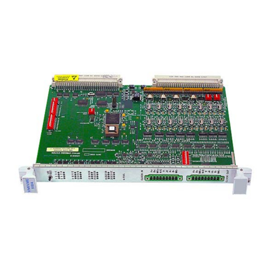
ABACO VMIVME-1184 Series Hardware Reference Manual (46 pages)
32-bit Optically Isolated Change-of-State (COS) Input Board with Sequence-of-Events (SOE)
Brand:
ABACO
| Category:
I/O Systems
| Size: 3.65 MB
Table of Contents
Table of Contents
9
1 Theory of Operation
13
Introduction
13
Vmebus Interface
14
Figure 1-1 VMIVME-1184 Block Diagram
14
Data Transfer Cycles
15
Figure 1-2 AM2 Line (Switch S29)
15
Interrupt Acknowledge Cycles
15
Register Decoder
16
Debounce
16
Change-Of-State Logic
17
Previous State Data Algorithm
17
Simultaneous" Data Changes, and the Debounce "Stretching" Effect
17
Table 1-1 COS Logic
17
Table 1-2 Walking Ones Test
17
Inputs
19
Voltage Sensing
19
Figure 1-3 Channels 1-30 Input Circuitry
19
Contact Closure
20
Table 1-3 Contact Closure SIP Resistors and Switch Assignments
20
Figure 1-4 Channel 31 Input Circuitry (Channel 32 Uses Vext #2)
21
2 Configuration and Installation
22
Introduction
22
Unpacking Procedures
22
Physical Installation
22
Before Applying Power: Checklist
22
Operational Configuration
23
Factory Installed Switches/Jumpers
23
Board Address and Address Modifier Selection
23
Figure 2-1 Switch and Jumper Locations
24
Debounce Timing
25
Input Configurations
25
Table 2-1 Voltage Thresholds
25
Table 2-2 Jumper E3 (Extended Debounce Timing)
25
Connector Description
26
Barrier Terminal Transition Panels
26
Figure 2-2 P1/P2 Connector Pin Layout
27
Table 2-3 P1 Pin Assignments
27
Table 2-4 P2 Pin Assignments
28
3 Programming
30
Introduction
30
Table 3-1 VMIVME-1184 Address Map
30
Board ID (BD ID) Register
31
Control and Status Registers
31
CSR1 Bit Definitions
31
Table 3-2 Board ID Register Bit Map
31
Table 3-3 Control and Status Register 1 Bit Map
31
CSR2 Bit Definitions
32
Table 3-4 Correlating Debounce Times
32
Table 3-5 Control and Status Register 2 Bit Map
32
Counter Connectivity
33
Quadrature Counter Decoder Bits (Bits 16, 17 and 18)
33
Encoder Markers
34
Data FIFO Register
35
Interrupt Processor Control Register
35
Table 3-6 Data FIFO Register Bit Map
35
Table 3-7 Interrupt Processor Control Register Bit Map
35
Interrupt Levels
36
Interrupt Processor COS Vector Register (Offset: $XXXX0D)
36
Interrupt Processor Marker Vector Register (Offset: $XXXX0E)
36
Counter FIFO Register (Offset: $XXXX10)
36
Table 3-8 Interrupt Level Bits
36
Cos Sel B/A
37
Counter Register (Offset: $XXXX14)
37
Figure 3-1 COS and SOE Registers
37
Table 3-9 COS SEL B/A
37
COS Select Register 0
38
COS Select Register 1
38
COS Select Register 2
38
COS Select Register 3
38
FIFO Count Register (FIFO_CNT)
38
Table 3-10 COS Select Register 0 Bit Map
38
Table 3-11 COS Select Register 1 Bit Map
38
Table 3-12 COS Select Register 2 Bit Map
38
Table 3-13 COS Select Register 3 Bit Map
38
Counter FIFO Count Register (CTR_FIFO_CNT)
39
Channel Interrupt Enable Register (CH_INT_ENA)
39
Firmware Revision Register (FREV)
39
Table 3-14 FIFO Count Register Bit Map
39
Table 3-15 Counter FIFO Count Register Bit Map
39
Table 3-16 Channel Interrupt Enable Register Bit Map
39
Counter Feature
40
Counter Operation
40
CSR1_[5, 4] Definitions
40
Table 3-17 Differential Termination (S28)
40
Quadrature Mode
41
Figure 3-2 Leading Edge Example
41
Figure 3-3 1X Counter Mode
41
Figure 3-4 2X Counter Mode
41
Figure 3-5 2X Quadrature
41
Quadrature Mode
42
Initialization
42
Figure 3-6 4X Quadrature
42
VMIVME-1184 Inputs
43
Table 3-18 Example Setup of the VMIVME-1184
43
Table 3-19 Input Connectivity
43
Marker Gating
44
Figure 3-7 Marker Gating Diagram
44
Advertisement
Advertisement
Related Products
ABACO VMICPCI-7055
ABACO Categories
PCI Card
Control Unit
Single board computers
I/O Systems
Lifting Systems
More ABACO Manuals
Login
Sign In
OR
Sign in with Facebook
Sign in with Google
Upload manual
Upload from disk
Upload from URL