Sign In
Upload
Manuals
Brands
AAON Manuals
Air Conditioner
RQ SERIES
AAON RQ SERIES Manuals
Manuals and User Guides for AAON RQ SERIES. We have
2
AAON RQ SERIES manuals available for free PDF download: Installation Operation & Maintenance, Manual
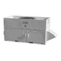
AAON RQ SERIES Installation Operation & Maintenance (100 pages)
Packaged Rooftop Units, Heat Pumps, & Outdoor Air Handling Units
Brand:
AAON
| Category:
Air Conditioner
| Size: 1 MB
Table of Contents
Table of Contents
3
AAON® RQ Series Features and Options Introduction
7
Safety
8
RQ Series Feature String Nomenclature
13
General Information
22
Codes and Ordinances
22
Receiving Unit
23
Figure 1 - Lockable Handle
23
Packaged Direct Expansion (DX) Units
24
Gas or Electric Heating
25
Table 1 - Electric and Gas Heating Capacities
25
Wiring Diagrams
26
Condensate Drain Pan
26
Table 2 - Auxiliary Electric Heating Capacities
26
Installation
27
Unit Location
27
Setting the Curb
27
Table 3 - Unit Clearances
27
Figure 2 - RQ Series Orientation
27
Figure 3 - RQ Cabinet Standard and Power Exhaust Gasket Locations
29
Forklifting the Unit
30
Figure 4 - Forklifting an RQ Series Unit from the Side
30
Figure 5 - Forklifting an RQ Series Unit from the Front
30
Lifting the Unit
31
Figure 6 - Lifting Details of a 2-6 Ton Standard or Power Exhaust Unit
31
Figure 7 - Lifting Details of a 2-6 Ton Energy Recovery Wheel Unit
31
Vertical Duct Connection
32
Figure 8 - Vertical Duct Connection
32
Seismic Curb Installation
33
Figure 9 - Solid Bottom Seismic Curb with Filters
33
Figure 10 - Seismic Solid Bottom Curb Without Filters Cross Section
34
Figure 11 - Seismic Solid Bottom Curb Without Filters Detail a
34
Figure 12 - Seismic Solid Bottom Curb Without Filters Detail B
34
Horizontal Duct Connection
35
Outside Air Rain Hood
35
Figure 13 - Seismic Rigid Mount Curb Cross Section
35
Figure 14 - Horizontal Duct Connections
35
Metal Mesh Filters
36
Figure 15 - RQ Series Unit Closed Rain Hood
36
Figure 16 - RQ Series Unit Open Rain Hood
36
Figure 17 - Rain Hood with Metal Mesh Filter Rack Installation
36
Electrical
37
Figure 18 - Unit Base Utility Entry
37
Figure 19 - Back View of Power Switch from Control Compartment
37
Table 4 - Single Circuited Variable Speed Compressor Frequency Range
39
Table 5 - Control Wiring
39
Thermostat Control Wiring
39
Variable Speed Compressors
39
Gas Heating
40
Maximum Piping Capacities
40
Table 6 - 2-6 Ton Gas Connections
40
Table 7 - Natural Gas (Ft 3 /Hr)
40
Figure 20 - RQ Series Gas Heat Exchanger
40
Piping Sizing Examples
41
Inlet and Manifold Pressures
41
Table 8 - Propane (Kbtu/Hr)
41
Gas Pressure Regulator & Overpressure Protection Device
42
Additional Gas Piping Considerations
42
Table 9 - Gas Piping Supports
42
Figure 21 - Example 2-6 Ton through the Base Gas Piping
43
Leak Testing
44
Refrigerant-To-Water Heat Exchanger
44
Water-Source Heat Pump Applications
44
Open Loop Applications
45
Freezing Water in the Heat Exchanger
45
Water Piping
46
Table 10 - Glycol Freezing Points
46
Table 11 - Condenser Water Connections
46
Condensate Drain Piping
48
Discharge and Suction Line Piping
48
Figure 22 - Post Corner Hole Location
49
Figure 23 - Post Back Hole Location
49
Figure 24 - Post Corner Hole Piping
50
Figure 25 - Post Back Hole Piping
50
Heating Coils
51
Chilled Water Coil
51
Table 12 - Hot Water Coil Connection Sizes
51
Table 13 - Steam Coil Connection Sizes
51
Table 14 - Chilled Water Coil Connection Sizes
51
Electric Preheat
52
Status Display Screens
52
Figure 26 - Preheat Controller
52
System Setting Screens
53
Table 15 - Stages of Electric Preheat
54
LED Flash Alarm Codes
55
Operation
55
Energy Recovery Units
56
Startup
64
Filters
64
Adjusting Refrigerant Charge
64
Checking Liquid Sub-Cooling
65
Checking Evaporator Superheat
65
Adjusting Sub-Cooling and Superheat Temperatures
65
Table 16 - Acceptable Refrigeration Circuit Values
65
Table 17 - R-410A Refrigerant Temperature-Pressure Chart
66
Gas Heater Instructions
67
Figure 27 - Gas Heater Instructions
67
Freeze Stat Startup
68
Supply Fan EC Motor Startup
68
Figure 28 - PIN Connectors on EC Supply Fan Motor Electronics
68
Condenser Fan EC Motor Startup
69
Table 18 - EC Condenser Fan Cycling Options
70
Adjustable Fan Cycling Switch Procedure
71
Operation
73
Thermostat Operation
73
Packaged DX Cooling Operation and Control
73
Gas Heater Operation
73
Electric Heating Operation
74
Steam or Hot Water Preheating and Heating Operation
74
Modulating Electric Preheat
74
Chilled Water or Non-Compressorized DX Cooling Operation
74
Maintenance
74
Gas Heating
74
Gas Heat Exchanger Removal
75
DX Cooling
76
Condenser Fan
76
Condensate Drain Pans
76
Figure 29 - Gas Heat Exchanger
76
Figure 30 - Removal of a Condenser Fan Assembly
76
Evaporator Coil
77
E-Coated Coil Cleaning
77
Figure 31 - Evaporator Coil Access
77
Microchannel Coil Cleaning
79
Supply Fan
81
Figure 32 - 2-6 Ton Supply Fan
81
Figure 33 - RQ Supply Fan Removal Bolts
81
Figure 34 - RQ Supply Fan Removal Slide
82
Variable Capacity Compressor Controller
84
Table 19 - Demand Signal Vs. Compressor Capacity Modulation
84
Figure 35 - Variable Capacity Compressor Controller
84
Filter Replacement
85
Table 20 - RQ Series 2-6 Ton Pre Filters
85
Figure 36 - Compressor Controller Flash Code Details
85
Replacement Parts
86
Table 21 - RQ Series 2-6 Ton Unit Filters
86
Table 22 - RQ Series 2-6 Ton Energy Recovery Wheel Filters
86
Figure 37 - RQ Series 2-6 Ton Standard Filter Layout
86
Appendix A - Heat Exchanger Corrosion Resistance
87
Appendix B - Thermistor Temperature Vs. Resistance Values
89
RQ Series Startup Form
90
Maintenance Log
94
Literature Change History
95
Advertisement
AAON RQ SERIES Manual (36 pages)
Variable Speed Scroll Compressor Supplement
Brand:
AAON
| Category:
Industrial Equipment
| Size: 1 MB
Table of Contents
Variable Speed Scroll Compressor Supplement
1
Table of Contents
2
RQ Series Variable Speed Compressor Components
5
Introduction
8
Variable Speed Scroll Compressors
8
Product Description
8
Compressor Motor
8
Oil Pump
8
Compressor Temperature Protection
8
Oil Recovery
8
Motor Protection
8
Starting and Stopping Routine
8
Oil Type
9
Maximum Tilt Angle
9
Contaminant Control
9
Discharge Check Valve
9
Electrical Troubleshooting
10
Figure 1 - Variable Speed Scroll Design Features
10
Figure 2 - Motor Winding Diagram
10
Three Phase Series Variable Speed Drives
11
Product Description
11
Theory of Drive Operation
11
Nomenclature
11
Temperature & Humidity
11
Power On/Off
11
Communication Setting
11
Input Voltage and Input Current
12
Power Factor Correction
12
Speed Control
12
Fault Clearing
12
Status Indication
12
LED for COMMS MCU
12
Drive over Temperature Protection
13
Power Interrupt
13
Air Cooled Heat Exchanger
13
Foldback
13
Troubleshooting
13
Table 1 - Troubleshooting - Fault and Protection
14
Figure 3- Electronics Nomenclature
16
Figure 4 - U.S. Drive Model Wiring Diagram
17
Figure 5 - U.S. Wiring Diagram
17
Table 2 - Communication Connector Pin Definition
18
Table 3 - Sensor Connector Pin Definition
18
Table 4 - Ramp up Procedure
19
Table 5 - Ramp down Sequence
19
Table 6 - Input Current Foldback
20
Table 7 - Output Current Foldback
20
Table 8 - Inverter Temperature Feedback
20
Variable Speed Compressor Temperature Control
21
Figure 6 - Wattmaster VCC-X Controller and Refrigeration System Control Module
21
Modular Silicon Expansion Valve and Universal Superheat Controller/Sensor Hardware Installation
22
Additional Product Markings for USHC-G1.3B and USHS-G1.3B
22
About the MSEV and USHX
22
Figure 7 - Modular Silicon Expansion Valve
22
Figure 8 - USHX
22
Figure 9 - USHZ Wiring Harness
22
Table 9 - USHX and Wiring Harness Pin Assignments
23
Mechanical Installation
24
Figure 10 - MSEV and USHC Installation Schematic
24
Figure 11 - MSEV Installation Orientation
25
Figure 12 - USHX Installation Orientation on a Horizontal Copper Line
26
Figure 13 - USHX Installation Orientation on Vertical Copper Line
26
Figure 14 - Brazed Access Fitting
26
Figure 15 - Installed USHX with Attached 10-Pin Wiring Harness
27
Figure 16 - Thermistor Installation at Evaporator Outlet
27
Electrical Wiring
28
Figure 17 - Insulation Secured to the Thermistor
28
Figure 18 - Class 2 DC and AC Power Sources
29
Figure 19 - Single USHC-MSEV or Single USHS Wiring Diagram
30
Figure 20 - USHX-To-RS485 Converter Connection
31
Figure 21 - MSEV Electrical Connections
31
Troubleshooting
32
Advertisement
Related Products
AAON RL Series
AAON RQ-002
AAON RQ-003
AAON RQ-004
AAON RQ-005
AAON RQ-006
AAON RQ NextGen Series
AAON RQ NEXT GEN Series
AAON R69190
AAON RZ-140
AAON Categories
Controller
Control Unit
Air Handlers
Heat Pump
Air Conditioner
More AAON Manuals
Login
Sign In
OR
Sign in with Facebook
Sign in with Google
Upload manual
Upload from disk
Upload from URL