Table of Contents
Advertisement
Advertisement
Table of Contents
Troubleshooting

Subscribe to Our Youtube Channel
Related Manuals for AAON RQ Series

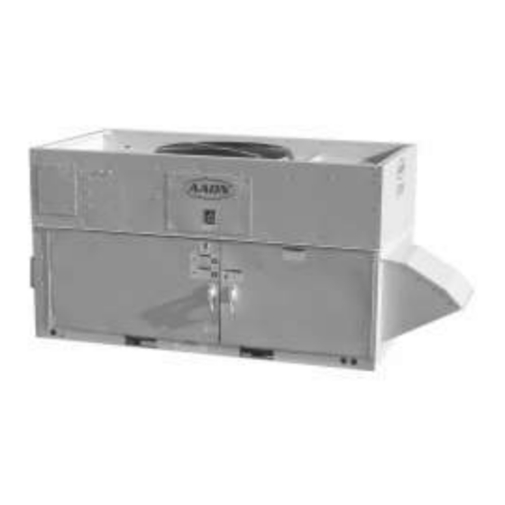
Summary of Contents for AAON RQ Series
-
Page 1: Variable Speed Scroll Compressor Supplement
RQ SERIES Variable Speed Scroll Compressor Supplement... -
Page 2: Table Of Contents
Table of Contents Variable Speed Scroll Compressor Supplement ................1 RQ Series Variable Speed Compressor Components ..............5 Introduction ............................. 8 Variable Speed Scroll Compressors....................8 Product Description ........................8 Compressor Motor ........................8 Oil Pump ............................. 8 Compressor Temperature Protection ..................8 Oil Recovery .......................... - Page 3 Index of Tables and Figures Tables: Table 1 - Troubleshooting – Fault and Protection ................ 14 Table 2 - Communication Connector Pin Definition ..............18 Table 3 - Sensor Connector Pin Definition ................... 18 Table 4 - Ramp Up Procedure ...................... 19 Table 5 - Ramp Down Sequence ....................
-
Page 5: Rq Series Variable Speed Compressor Components
RQ Series Variable Speed Compressor Components Electronic Expansion Valve Inverter WattMaster VCC-X Controls Variable Speed Compressor EC Motor Automation Control Unit... - Page 6 Variable Speed Compressor Inverter WattMaster VCC-X Controls Electronic Expansion Valve Controller Condenser Fan EC Motor Automation Control Unit...
- Page 7 Example Wiring Diagram showing WattMaster Refrigeration System Module for Variable Speed Compressors, Copeland Inverter, Electronic Expansion Valve, and Variable Speed Condenser Fan Control...
-
Page 8: Introduction
Introduction Compressor Temperature Protection A discharge line thermistor must be used to This document provides instructions on how protect the compressor. The drive will shut the variable speed scroll compressor and down the compressor when the thermistor inverter drive are applied to a variable speed temperature exceeds 275°F (135°C). -
Page 9: Oil Type
Oil Type Contaminant Control Variable speed scrolls are charged with Moisture levels should be maintained below polyolester (POE) oil. See the compressor 50 ppm for optimal performance. A filter- nameplate for the original oil charge. A drier is required on all R-410A and POE complete recharge should be approximately lubricant systems... -
Page 10: Electrical Troubleshooting
Electrical Troubleshooting Caution Caution Energizing a variable speed scroll with a grounded winding can cause Bypassing the variable frequency irreversible damage to the drive. drive and connecting AC line voltage directly to the compressor can cause irreversible damage Measuring the current in the three individual compressor. -
Page 11: Three Phase Series Variable Speed Drives
Temperature & Humidity WARNING Drive operating temperature range: -20°C to 60°C Electric shock hazard. Disconnect and lock power before servicing. Drive storage temperature range: Discharge capacitors before -40°C to 85°C servicing. Maximum Relative Humidity: 95% Three Phase Series Variable Speed Caution Drives Check the drive carefully before using it. -
Page 12: Input Voltage And Input Current
Input Voltage and Input Current Fault Clearing The drives are designed for rated AC power Faults are cleared through unit controls supply: 50/60Hz, 380-480V on EV20XXM interface. KX-XXX models 208-240V Status Indication EV20XXM-JX-XXX drive models. There are two control chips on the drive board and all of them have their own LED AC Input Overcurrent Drive... -
Page 13: Drive Over Temperature Protection
Drive Over Temperature Protection The drive is self protected against high • Immediate shutdown = The drive will internal temperatures. There are different execute an immediate shut down due to a modes of protection; temperature high and condition that may cause damage to the foldback. -
Page 14: Table 1 - Troubleshooting - Fault And Protection
Table 1 - Troubleshooting – Fault and Protection Comms Led Fault and Blink Code Description Check and Handling Protection LED604 LED603 Check the compressor U/V/W and the PIM module. Make Compressor Compressor phase sure the circuit is not short. phase over- instant over-current 1 or 3 Check the compressor U/V/W connection;... - Page 15 Comms Led Blink Code Fault and Description Check and Handling Protection LED604 LED603 Compressor loss of Lost rotor Check the compressor U/V/W connection. Check system phase, rotor locked, position charge levels, if too high this problem can occur. lost rotor position. Check the AC power supply and if the right voltage is DC bus Voltage is below the...
-
Page 16: Figure 3- Electronics Nomenclature
Comms Led Fault and Blink Code Description Check and Handling Protection LED604 LED603 AC input voltage Sensor on drive not reading properly. Replace the drive sampling fault DC BUS voltage Sensor on drive not reading properly. Replace the drive sampling fault AC input lost of phase Input missing phase... -
Page 17: Figure 4 - U.s. Drive Model Wiring Diagram
Figure 4 - U.S. Drive Model Wiring Diagram Figure 5 - U.S. Wiring Diagram... -
Page 18: Table 2 - Communication Connector Pin Definition
Table 2 - Communication Connector Pin Definition Pin Number Description Figure RS485 (+) Not Used Not Used RS485 (-) Common EMI Drain Wire Table 3 - Sensor Connector Pin Definition Pin Number Description Figure Sensor Pin 3.3VDC Not Used Not Used High Pressure Signal 3.3VDC... -
Page 19: Table 4 - Ramp Up Procedure
Table 4 - Ramp Up Procedure Stage Description Target Frequency Ramp Up Rate Duration (Hz) (Hz/s) Compressor command started. Compressor reaches minimum start frequency. Compressor remains at platform frequency. Compressor reaches commanded frequency. Commanded Table 5 - Ramp Down Sequence Stage Description Target Frequency... -
Page 20: Table 6 - Input Current Foldback
Table 6 - Input Current Foldback Condition Action taken by the Drive Input Current >= Foldback Current Will reduce the speed to minimum speed at rate of 20 rpm/s Recovering Current <= Input Current <Foldback Will remain in the current speed Current Input Current <... -
Page 21: Variable Speed Compressor Temperature Control
Variable Speed Compressor Temperature Control WattMaster VCC-X Unit Controller and Cooling Mode Operation WattMaster Refrigerant System Module for In the Cooling Mode, as the Supply Air Copeland VFD Compressors (RSMVC-P) Temperature (SAT) rises above the Active work together to control the unit operation SAT Cooling Setpoint, the compressors will and control the variable speed compressor stage on and modulate to maintain the... -
Page 22: Modular Silicon Expansion Valve And Universal Superheat Controller/Sensor Hardware Installation
Modular Silicon Expansion Valve and Universal SuperHeat Controller/Sensor Hardware Installation Universal SuperHeat Controller/Sensor Additional Product Markings for USHC- (USHX), shown in Figure 8 is offered either G1.3b and USHS-G1.3b as a: Operating Control Independently Mounted a. Universal SuperHeat Controller Pollution Degree 2 (USHC): To drive and control the Impulse Voltage: 300 V MSEV. -
Page 23: Table 9 - Ushx And Wiring Harness Pin Assignments
Table 9 - USHX and Wiring Harness Pin Assignments USHX – G1.3b Series Model Numbers USHC-G1.3b-BAAAXXX USHS-G1.3b-BAAAXXX Wiring Harness Model Pin Number Pin Name Pin Function Type of Wire WH-USHX-AX Pin 1 Power Input Red, 18 AWG Pin 6 Power Input Black, 18 AWG RS485- Black, 24 AWG,... -
Page 24: Mechanical Installation
Mechanical Installation This section describes the mechanical installation of the MSEV and USHX Figure 10 below shows an example of a typical system the MSEV and USHX devices would integrated into. Like conventional thermostatic expansion valves (TXVs) or electronic expansion valves (EEVs), the MSEV is installed at the inlet of the evaporator. -
Page 25: Figure 11 - Msev Installation Orientation
Installing the MSEV a. While brazing, direct heat install MSEV, complete away from the valve body. following steps: Ensure that the temperature of the valve body does not exceed 221°F (105°C). 1. Pump down and recover any residual 7. It is mandatory to install a brand new refrigerant from the system. -
Page 26: Figure 12 - Ushx Installation Orientation On A Horizontal Copper Line
Installing the USHX install USKX, complete following steps: 1. Pump down and recover any residual refrigerant from the system. This may have already been done if a MSEV was installed before this step. 2. Obtain any ¼” access fitting that is compatible with the system. -
Page 27: Figure 15 - Installed Ushx With Attached 10-Pin Wiring Harness
8. Mount the USHX onto the access 10. Install the thermistor at the outlet of fitting. Turn the USHX housing the evaporator and close to the clockwise by hand until some access fitting using a zip tie, as resistance is met and then use 7/16” shown below in Figure 16. -
Page 28: Electrical Wiring
11. Wrap thermistor with 20. Power on the HVAC/R system and insulation material and secure the MSEV USHX will insulation in place using a zip tie. automatically begin functioning. The final result should be similar to 21. Observe the superheat temperature what is shown below in Figure 17. -
Page 29: Figure 18 - Class 2 Dc And Ac Power Sources
2. Obtain Class 3. Double check the power source transformer with a capacity of 40 to output voltage (AC transformer 100 VA and an output of 24 VAC at secondary or DC power supply a frequency of 60 Hz. Alternatively, output). -
Page 30: Figure 19 - Single Ushc-Msev Or Single Ushs Wiring Diagram
4. Once the power source output b. The wiring schemes of the voltage has been identified and ‘Single USHC-MSEV Setup’ checked to be accurate, ensure that and ‘Single USHS Setup’ are the power supply is off before the same except that the continuing with the steps below. -
Page 31: Figure 20 - Ushx-To-Rs485 Converter Connection
6. Connect the RS485 communication wires (2-wire gray cord that contains 9. The general purpose wires (20 AWG a red and a black wire and the green brown/purple wires), if they exist on data ground wire) to the D+, D-, and the harness, must remain SG terminals on the USB-to-RS485 unconnected, be terminated with... -
Page 32: Troubleshooting
Troubleshooting The following section describes troubleshooting procedures for the USHX and MSEV. If the system is running abnormally, first check the wiring for broken or shorted connections. Repair broken wires and remove short circuits between touching wires or between wires and any metal surfaces. - Page 36 Variable Speed Scroll Compressor Supplement V83980 · Rev. A · 170111 It is the intent of AAON to provide accurate and current product information. However, in the interest of product improvement, AAON reserves the right to change pricing, specifications, and/or design of its product without notice, obligation, or liability.
Need help?
Do you have a question about the RQ Series and is the answer not in the manual?
Questions and answers