
Related Manuals for Worcester GREENSOURCE 6 kW


Summary of Contents for Worcester GREENSOURCE 6 kW
-
Page 1: Installation Manual
WORCESTER GREENSOURCE 6 kW, 7 kW & 9.5 kW HEAT PUMP WITH HOT WATER DISTRIBUTION UNIT GB/IE GB/IE INSTALLATION MANUAL Please read carefully prior to installation and user guide... -
Page 2: Building Regulations
(Scotland) Regulations 1990. Regulation 10 (B2), 22 (J3.3a and J3.4), 27 and 28 (P2.6 and P3). The Building Regulations (Northern Ireland) 2000. Installation manual for the Worcester Greensource heat pump with hot water distribution unit Worcester, 16.06.08 Part number: 8-716-115-330 Issue: a Copyright ©... -
Page 3: Table Of Contents
Table of Contents Contents FOR THE INSTALLER .................... 5 Important information to the installer ................6 Checklist ........................6 What the deliver y includes .....................7 General .........................8 Transporting and storage ................................8 Positioning the heat pump ................................8 Minimum and maximum working temperatures ..........................9 Different methods of heating control ............................... - Page 4 PRODUCT CONTENTS LIST Greensource Heat Pump. Components included in deliver y: Literature pack: Rubber feet User manuals Outdoor sensor T2 with cable Installation manual Room sensor T5 Guarantee card Valve with fi lter Circlip pliers Flexible connection hoses Tundish (factory fi tted) Unvented cylinder kit: DHW expansion vessel Expansion Vessel Hose...
-
Page 5: For The Installer
For the Installer This guide provides the heat pump installer with a description of how the heat pump and the Hot water distribution unit (HWDU) are installed and commis- sioned. The installation section consists of a plumbing part and an electrical part. -
Page 6: Important Information To The Installer
Important information to the installer / Checklist Important information to the installer This manual gives you all the information necessary to install the heat pump Note and HWDU. The guide is divided into several parts in the order in which installation and commissioning must be carried out. -
Page 7: What The Delivery Includes
What the delivery includes What the delivery includes The following components are included in the delivery of the heat pump and HWDU: Valve with fi lter Rubber feet Quantity: 1 Quantity: 4 Outdoor sensor T2 (GT2) with cable Literature pack Quantity: 1 User manual Greensource Heat pump User manual Hot water distribution unit... -
Page 8: General
General General Transporting and storage The heat pump should always be transported and stored in an upright position. Otherwise the suspension fi ttings inside the compressor can be damaged. If the heat pump must be tilted during entry to the installation site, this should be done for as short a time as possible. -
Page 9: Minimum And Maximum Working Temperatures
General Minimum and maximum working temperatures Maximum working temperatures The heat pump can work with a maximum return temperature of approxi- mately 59ºC. If the temperature rises above this value the heat pump will stop for reasons of technical safety. In the event of additional heat only, the maximum fl... -
Page 10: Location Of The Temperature Sensors
General Location of the temperature sensors Flow sensor Outdoor sensor Hot water sensor Room sensor Sensor compressor temperature Sensor heat transfer fluid out Sensor heat transfer fluid in T10 Sensor condenser temperature T11 Sensor refrigerant temperature evaporator T12 Sensor air temperature evaporator Heating system 3-way... -
Page 11: Canbus
General CANbus The Rego 800 has different circuit boards which are connected by a communications cable, CANbus. CAN is an abbreviation of Controller Area Warning Network and is a two wire system for communication between the micro- processor based modules/circuit boards. These are connected in series. The CANbus cable must be screened The heat pump has one circuit board (IOB circuit board), other circuit and laid separately from the power... -
Page 12: Components Identifi Cation
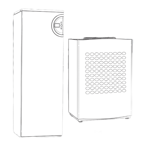
General Components identifi cation Hot water distribution unit Mixing valve Pressure gauge Heat carrier (0.5 – 1.5 bar) pump (G2) Pipes to and from the heat pump are con- nected at the back Pump for heating Three-way Three-way system (G1) valve valve Heat pump... -
Page 13: Dimensions, Clearance And Plumbing Connections
Dimensions, clearance and plumbing connections Dimensions, clearance and plumbing connections Greensource Air to water heat pump (outdoor) Left-hand side Front Back Condensator drain Cable entry 1) Flow to HWDU 2) Return from HWDU 1190 Note Required installation space for the heat pump. Minimum distance from the pump to the wall is 300 mm. -
Page 14: Fit The Fi Lter Valve
Dimensions, clearance and plumbing connections Pipe connections HWDU front view The following connections are made to the HWDU: A 32 mm plastic pipe is taken from the waste water pipe to the fl oor drain. The fl ow is connected to the inlet marked For ward fl ow. The return is connected to the inlet marked Return fl... -
Page 15: Connecting To The Heating System
Connecting to the heating system Connecting to the heating system Fitting the unvented kit Parts to assemble: High fl ow rate inlet control set Expansion vessel Expansion vessel hose Tundish - factor y fi tted Tundish - 15mm x 22 mm supplied separately Wall mounting kit for expansion vessel Blending valve... - Page 16 Connecting to the heating system Detailed discharge pipe installation requirements The discharge pipework must be routed in accordance with part G3 of schedule 1 of the building Regulations. The tundish should be vertical, located in the same space as the unvented hot water cylinder and be as close as possible and within 500mm of the safety device e.g.
- Page 17 Connecting to the heating system Maximum length of Deduct the fi gure below from the Size of discharge Size of discharge Valve outlet size straight pipe maximum length for each bend or pipework D1 pipework D2 (no bends or elbows) elbow in the discharge pipe 22 mm Up to 9 m...
-
Page 18: Flushing The Heating System
Connecting to the heating system Flushing the heating system It is important that all previously mentioned preparations have been carried out before the heat pump is connected to the heating system. Also ensure the heating system has been well fl ushed before the heat pump is installed. Flushing protects Note the heat pump from contamination. -
Page 19: Principle Method Of Operation
Connecting to the heating system Principle method of operation The principle method of operation is based on the vapour compression cycle with any additional heat being provided by the built in electric heater. The control unit controls the heat pump using the outdoor sensor T2 and the fl ow sensor T1 according to the set heat curve. -
Page 20: Filling The Heating System
Connecting to the heating system Filling the heating system Warning The hot water cylinder must always be After fl ushing the heating system the hot water cylinder must be fi lled fi rst fi lled and pressurised before the heat- and then the heating system can be fi... -
Page 21: Isolation Switch And Residual Current Device
Connecting to the power supply Isolation switch and residual current device Isolation switch All heating installations must be preceded by a safety switch. Residual current device It is recommended that a separate residual current device is fi tted to the heating system. -
Page 22: Wiring Diagram Greensource Heat Pump
Wiring diagram Wiring diagram Greensource heat pump... -
Page 23: Wiring Diagram Greensource Hwdu
Wiring diagram Wiring diagram Greensource HWDU Display card Open Open Close To the heat pump 1) Jumper S1 must be in "Term" position on the fi rst and last circuit board in the CANbus loop. Electric heater 4.5 kW Miniature circuit breaker F21: Overheat protection elecrical heater F31:... -
Page 24: Terminal Diagram Greensource Heat Pump - Hwdu
T2: Outdoor sensor T5: Room sensor Isolation switch, not included. It is recommended that a separate residual current device is fi tted to the heating system. Fusing: Greensource 6 kW: 16A Greensource 7 kW: 25A Greensource 9.5 kW: 25A HWDU: 25A... -
Page 25: External Connections Greensource Heat Pump
External connections External connections Greensource heat pump Power supply: Connect to terminals L1, N and PE. CANbus: Warning Communication cable between the heat pump and HWDU. Connect to terminals GND, CANL, CANH and 12V. See more under section Do not mix up the 12V and CAN- CANbus. -
Page 26: External Connections Greensource Hwdu
External connections External connections Greensource HWDU Power supply: Connect to terminals L3, N and PE. Warning CANbus: Communication cable between the heat pump and HWDU. Connect Do not mix up the 12V and CAN- to terminals GND, CANL, CANH and 12V. See more under section bus connections! If 12V (or other incorrect voltage) is supplied to the CANbus. -
Page 27: Installer And Service Menu (I/S)
Installer and service menu Installer and service menu (I/S) First read about Commissioning. Warning As the installer you have your own section of menus for settings, e.g. for commissioning and maintenance. The installer and service menu (I/S) is only for installers. Under no circum- stances may the user access this level. -
Page 28: Menu Overview
Menu overview Menu overview Here you fi nd the upper levels for all functions under Menu and Advanced menu. All setting functions can also be found in the table Factory settings, see Technical information. Menu Start up Setting the clock Connected extra sensors Connection capacity Manual operation... -
Page 29: Advanced Menu
Menu overview Advanced menu Heating system temperature Temperature Room sensor settings (T5) Time limited settings Heating season Heating, maximum operating time at hot water requirement Shut down protection, change over hot water to heating Compressor working area settings Extra hot water Hot water Hot water peak K, I/S... - Page 30 Menu overview Setting the clock Set date Set time Alarm Alarm log K, I/S Alarm history Warning log K, I/S Access level Return to factor y settings K, I/S Deactivate alarm buzzer K, I/S Program version...
-
Page 31: Commissioning
Commissioning Commissioning Before commissioning the heating system must be fi lled up and completely vented. Check that there are no leaks. As many radiators as possible should be fully open when connecting to an existing water system. When connecting to an underfl oor heating system at least half of all the fl... -
Page 32: Manual Operation
Commissioning Connected extra sensors Yes must apply for T5 acknowledged when room sensor T5 is used. Connection capacity Important and must be changed State total output: Setting of total connected output on the additional heat. The factory setting is 13.5 kW. Change this to 4.5 kW. Compressor mode, output limitation: Setting permitted output when the compressor is in operation. -
Page 33: Forced Defrost
Commissioning Fan defrost inter val and Fan defrost time Because weather conditions vary from place to place some factory settings for defrosting may need adjustment. This particularly applies to locations with high humidity where there is a risk that the fan will ice up. Fan defrost means that warm air is blown upwards through the fan. -
Page 34: Other Settings
Commissioning Display The function affects the window contrast and brightness. On delivery the max setting 10 is set on both. Alarm during start up During start up there may be an alarm regarding Low temperature in condenser. The cause is that the fi lled water is too cold (colder than +5ºC). Check the sight glass inside the heat pump. -
Page 35: Timers
Advanced menu Timers There are a number of timers in the control unit. The status for these are shown in the menu Timers. Extra hot water Heating, maximum operating time at hot water require- Displays the remaining time for requested extra hot water. ment Displays the remaining time before the maximum time in heating mode is reached if there is a simultaneous hot water... -
Page 36: Alarm Functions
Advanced menu Alarm functions Functions under Alarm: Alarm log Alarm history Warning log All alarms and warnings are described in the User guide. At Customer level you have access to alarm information in the alarm log. As installer you can also: Delete the Alarm log Read information in Alarm history Read information in Warning log... -
Page 37: Commissioning Report
Commissioning report Client / Installation address: Installer: Heat pump description: Commissioning date: Heat pump serial number: HWDU serial number: Other components of the installation: Outdoor sensor T2 Room sensor T5 ................Hot water cylinder temperature ........sensor T3 Others: ..........................................Points to be checked prior to commissioning Heating system Notes: ............ - Page 38 Commissioning report System pressure levels checked ..................... Functional test carried out ..................... Ensure that primary circuit has been correctly fl ushed ..................... Check fan operation on outdoor unit ..................... Check for insulation of pipe work ..................... Check that CANbus is fi tted correctly .....................
-
Page 39: Technical Information
Technical information Technical information Factory settings The table displays the factory values (F value) of the settings that you, as a customer, (K) can change via the customer menus Menu and Advanced menu. The functions of Installer/Service level (I/S) under Menu and Advanced menu in the table are accessed by the installer after changing the access level. - Page 40 Technical information Advanced menu Advanced menu Level F value Level F value Temperature Hot water --"--\Heating system temperature --"--\Extra hot water V=20,0ºC, --"--\ --"--\Number of hours --"--\ --"--\Heat curve H=55,2Cº --"--\ --"--\Stop temperature 65,0ºC --"--\ --"--\Hysteresis --"--\ --"--\ --"--\Maximum 16,0ºC --"--\Hot water peak --"--\ --"--\ --"--\Minimum 4,0ºC...
- Page 41 Technical information Advanced menu Advanced menu Level F value Level F value --"--\Fan defrost --"--\Mixing valve settings --"--\ --"--\Fan defrost interval 1 time --"--\ --"--\Neutral zone 1,0ºC --"--\ --"--\Fan defrost time 1,0 min --"--\ --"--\Running time extension --"--\ --"--\Temperature limit -5ºC --"--\ --"--\ --"--\Increase signal extension 1 time...
-
Page 42: Technical Information
Technical information Technical information Greensource 6 kW 7 kW 9.5 kW Emitted/Supplied output at +7/35º 5,5 / 1,5 7,1 / 2,1 8,8 / 2,3 Emitted/Supplied output at +7/45º 5,1 / 1,7 6,9 / 2,5 8,5 / 2,8 Heat carrier fl ow nominal 0,19 0,29 0,34... -
Page 43: Sound Levels
Heat pump Lp - ear (dBa) Sound pressure level: Greensource 6 kW Sound pressure level is defi ned as the sound level, which at an ear Greensource 7 kW level of 1.8 metres, is perceived one metre from the heat pump. -
Page 44: Supplimentary Technical Information
Technical information Supplementary technical information Maximum water supply pressure to the pressure reducing valve 16 bar Operating pressure DHW 3 bar Expansion vessel charge pressure 3 bar Expansion valve setting 6 bar Maximum primary working pressure 2,5 bar Set opening pressure of the combined temperature and pressure relief valve 7 bar / 95°C Expansion vessel, 19 Litres 3 bar... - Page 46 Part no: 8-716-115-330 Issue a 14658, Issue 1.0 EXCELLENCE COMES AS STANDARD Worcester, Bosch Group Cotswold Way, Warndon, Worcester WR4 9SW. Tel. 01905 754624 Fax. 01905 754619 W orcester, Bosch Group is a brand name of Bosch Thermotechnology Ltd. www.worcester-bosch.co.uk...
Need help?
Do you have a question about the GREENSOURCE 6 kW and is the answer not in the manual?
Questions and answers