Table of Contents
Advertisement
Quick Links
Download this manual
See also:
Repair Manual
Safety, Operation & Maintenance Manual
®
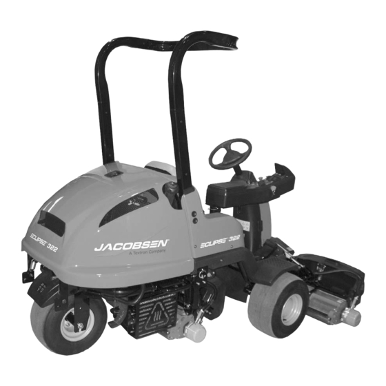
Eclipse
322 Riding Greens Mower with ROPS
62800 – Battery Power, 3WD
62801 – Battery Power, 2WD
62802 – Gas Hybrid Power, 3WD
62803 – Gas Hybrid Power, 2WD
62804 – Diesel Hybrid Power, 3WD
62805 – Diesel Hybrid Power, 2WD
62825 – Diesel Hybrid Power with Premium Seat, 2WD
62826 – Diesel Hybrid Power with Premium Seat, 3WD
62851 – Diesel Hybrid Power, 2WD
62852 – Diesel Hybrid Power with Premium Seat, 2WD
62853 – Diesel Hybrid Power, 3WD
62854 – Diesel Hybrid Power with Premium Seat, 3WD
WARNING: If incorrectly used this machine can cause severe injury. Those
who use and maintain this machine should be trained in its proper use, warned
of its dangers and should read the entire manual before attempting to set up,
operate, adjust or service the machine.
GB
United
Kingdom
WARNING
4187720-GB-Rev E
Advertisement
Table of Contents
Troubleshooting

Related Manuals for Jacobsen Eclipse 322


Summary of Contents for Jacobsen Eclipse 322
- Page 1 4187720-GB-Rev E Safety, Operation & Maintenance Manual ® Eclipse 322 Riding Greens Mower with ROPS 62800 – Battery Power, 3WD 62801 – Battery Power, 2WD 62802 – Gas Hybrid Power, 3WD 62803 – Gas Hybrid Power, 2WD 62804 – Diesel Hybrid Power, 3WD 62805 –...
-
Page 2: Table Of Contents
The serial plate is located on the rear frame rail. troubleshooting instructions, and parts list for your new Jacobsen recommends you record these numbers below Jacobsen machine. This manual should be stored with for easy reference. the equipment for reference during operation. - Page 3 BATTERIES ADJUSTMENTS Battery Safety............. 52 11.1 General .............. 81 Battery Conditioning ...........52 11.2 Bedknife-To-Reel ..........81 Battery Systems ..........54 11.3 Bedknife Adjustment ..........82 Battery Filling (Battery Powered Mowers) ..54 11.4 Cutting Height ............82 Battery Maintenance ..........55 11.5 Reel Assembly ...........83 Battery Performance ..........55 11.6 Reel Bearing ............84 Battery Disposal ..........55 11.7 Reel Stabilizer Rods ...........84...
-
Page 4: How To Operate Safely
Know the location and correct operation of controls. Operators without experience must receive instruction from another person that knows the correct operation of the equipment before you operate the mower. Only use parts, accessories and attachments approved by Jacobsen. SAFE OPERATION Inspect the mower before you operate the mower. -
Page 5: Safety
Look for traffic. Do not remove the ROPS from the mower. Stop the blades when the mower is on any surface Jacobsen must approve any changes to the that is not grass. ROPS. Do not release the cut grass in the direction of... -
Page 6: Maintenance And Storage
PTO switch to the OFF position, lower the Jacobsen. cutting unit to the ground, engage the parking To decrease the fire hazard, remove materials that brake, stop the engine and remove the key. burn from the engine, muffler, battery tray and fuel Make sure the mower is parked on a solid and level tank area. -
Page 7: Important Safety Notes
Adjustments and maintenance should always be performed by a qualified technician. If additional information or service is needed, contact your Authorized Jacobsen Dealer who is kept informed of the latest methods to service this equipment and can provide prompt and efficient service. -
Page 8: Specifications
SPECIFICATIONS SPECIFICATIONS PRODUCT IDENTIFICATION_________________________________________________ ® diesel engine power module, 62800 ......Eclipse 322, 3WD, 48 volt battery power module, power steering. power steering. Without mowers. ® Without batteries or mowers. 62852......Eclipse 322, 2WD, 13.3 hp T4 ® diesel engine power module, 62801 ...... -
Page 9: Hybrid Batteries
HYBRID BATTERIES _______________________________________________________ Buffer Battery Battery Brand Battery Part Number Full River is the Jacobsen recommended battery for use in Buffer Battery Set for the Eclipse 322 mower. Early Interstate SP-40 mowers used the Genesis G16 EP battery. Cranking Length... -
Page 10: Battery Power Module
Trojan T-890 battery is the Jacobsen recommended ordered separately. For optimum range and performance battery for use in the Eclipse 322 mower. use batteries that equal or exceed the Amp-hour rating Battery Brand Battery Part Number listed. -
Page 11: Declaration Of Conformity
Uzņēmuma nosaukums un pilna ražotāja adrese ▪ Verslo pavadinimas ir pilnas gamintojo adresas ▪ Isem kummerċjali u indirizz sħiħ tal-fabbrikant ▪ Jacobsen, A Textron Company Nazwa firmy i pełny adres producenta ▪ Nome da empresa e endereço completo do fabricante ▪... - Page 12 SPECIFICATIONS 62800: 2,1 kW @ 4650 RPM 62801: 2,1 kW @ 4650 RPM 62802: 9,69 kW @ 3600 RPM 62803: 9,69 kW @ 3600 RPM Net Installed Power ▪ Нетна инсталирана мощност ▪ Čistý instalovaný výkon ▪ Installeret nettoeffekt ▪ Netto geïnstalleerd vermogen ▪ 62804: 9,3 kW @ 3300 RPM Installeeritud netovõimsus ▪...
- Page 13 Ort und Datum der Erklärung ▪ Τόπος και ημερομηνία δήλωσης ▪ A nyilatkozat kelte (hely és idő) ▪ Luogo e data della dichiarazione ▪ Jacobsen, A Textron Company Deklarācijas vieta un datums ▪ Deklaracijos vieta ir data ▪ Il-post u d-data tad-dikjarazzjoni ▪ Miejsce i data wystawienia deklaracji ▪...
-
Page 14: Vibration Level
Information Supplied for Physical Agents Directive 2002/44/EC By reference to: Hand/Arm Standards: BS EN ISO 5349-1 (2001) BS EN ISO 5349-2 (2001) Eclipse 322 Hand/Arm Maximum Left Hand or Right Hand Accelerations m/s Acceleration Level Mean Value of X, Y, Z Aeq 0.75 ±... -
Page 15: Weights And Dimensions
2.10 ACCESSORIES & SUPPORT LITERATURE _____________________________________ Contact your area Jacobsen Dealer for a complete listing of accessories and attachments. CAUTION Use of other than Jacobsen authorized parts and accessories may cause personal injury or damage to the equipment. Accessories Rollers Traction Pedal Test Connector........ -
Page 16: Decals
DECALS DECALS DECALS _________________________________________________________________ Familiarize yourself with the following decals. They are critical to the safe operation of the mower. REPLACE DAMAGED DECALS IMMEDIATELY. 4181865 • Read operator's manual. Do not allow untrained • Before you clean, adjust, or repair this equipment, operators to use machine. - Page 17 DECALS Familiarize yourself with the following decals. They are critical to the safe operation of the mower. REPLACE DAMAGED DECALS IMMEDIATELY. DANGER To prevent injury, disengage all drives, engage parking brake, stop engine, and remove key before working on machine or emptying grass catchers.
- Page 18 DECALS WARNING (Diesel Hybrid Power Units Only) Radiator is under pressure. Remove cap slowly to avoid personal injury. 4181862 WARNING Read manual before performing maintenance. 4181863 IMPORTANT DO NOT USE STARTING ASSIST FLUIDS Use of starting assist fluids in the air intake system may be potentially explosive or cause a “runaway”...
- Page 19 DECALS Familiarize yourself with the following decals. They are critical to the safe operation of the mower. REPLACE DAMAGED DECALS IMMEDIATELY. 4216820 Rev A Disconnect Steering Chain before towing mower. en-19...
- Page 20 DECALS en-20...
- Page 21 DECALS Familiarize yourself with the following decals. They are critical to the safe operation of the mower. REPLACE DAMAGED DECALS IMMEDIATELY. en-21...
-
Page 22: Controls Icons
CONTROLS CONTROLS ICONS ___________________________________________________________________ Read Manual 48 VDC Battery 12 VDC Battery System Energize LDU Light LDU Light Mow Switch Lights Horn Reel Engine Oil System Power Parking Brake System Fault Glow Plug Pressure LDU Light LDU Light LDU Light LDU Light LDU Light Surface may be... -
Page 23: Instrument Panel
CONTROLS INSTRUMENT PANEL ______________________________________________________ A. LCD Display Unit (LDU) OFF Position - Power to mower is turned off, Used to display and set operating conditions. See automatic parking brake is applied. Section 4.5. RUN Position - Controllers active, normal operating mode. -
Page 24: Operator Controls
CONTROLS OPERATOR CONTROLS ____________________________________________________ K. Forward Traction Pedal P. Seat Adjustment Lever Press forward traction pedal down to move the mower Pull lever up and slide seat forward or backward. forward. The further the pedal is pressed, the faster the Release lever to lock seat in place. -
Page 25: Operator Convenience
CONTROLS OPERATOR CONVENIENCE _________________________________________________ T. MCU Access Panel Z. Center Reel Swing Arm Service Latch Remove thumbscrew and lift up on front of access panel Used to secure center reel swing arm in service to view MCU diagnostic lights. Always secure access position. -
Page 26: Lcd Display Unit (Ldu)
LDU indicates the diesel engine glow plugs are energized. Glow plug light has no function on battery or gas engine power module units. JACOBSEN Engine Oil Pressure Light: (Hybrid Power 12 V VERSION X.XX... -
Page 27: Alarm Codes
Reel motor operation is enabled, number of reel blades are set to 9, reel speed is set to The Jacobsen start up screen will display for 5 seconds 2200 rpm, and FOC is set to 0.196 in. (0.4967 cm). - Page 28 CONTROLS 4.5.6 Operator Mode____________________ Enter Pin? Screen: Used to enter Maintenance Mode. Enter the four digit pin number to access Maintenance Operator mode is used by the operator to view Mode. attachment mode, system voltage information, travel Alarms Screens: Used to view alarms stored in system speed, reel motor current, reel motor speed, switch memory.
- Page 29 NOTE: The Maintenance Mode PIN can be customized black button (AL) to enter set mode. Set reel direction for to a setting of your choice. Please contact your Jacobsen each reel, pressing black button to change between each Dealer or Jacobsen Technical Support (1800-848-1636 reel.
- Page 30 CONTROLS Switch Status: Displays the current switch settings, and 2WD/3WD Mode: pressing black button (AL) toggles is used to diagnose switch problems. A status of 0 mower between 2WD and 3WD modes. Do not set indicates the switch is in the OFF position. A status of 1 mower to 3WD if the 3WD system is not installed.
- Page 31 CONTROLS Maintenance MAINTENANCE Display Set number SELECT 15 BLADES Mode MODE units of reel UNITS? CHANGE? blades Displays system SYSTEM VOLTS Change Reel blade 15 BLADES voltage 48.0 VDC UNITS display setting < DONE > < ENGLISH > units Displays travel TRAVEL SPEED 2WD/3WD speed of mower...
-
Page 32: Frequency Of Cut
CONTROLS FREQUENCY OF CUT ______________________________________________________ The FOC (Frequency of Cut) is the distance, in inches Adjust FOC with Reel Speed Setting (cm), the machine travels forward between reel blades 1. Using the FOC charts, determine the maximum mow contacting the bedknife. The FOC can be adjusted either speed and fixed reel speed required for the desired by changing the Fixed FOC setting or by changing the FOC. - Page 33 CONTROLS 15 Blade Reel FOC Table Reel RPM Speed 1800 1850 1900 1950 2000 2050 2100 2150 2200 Inch Inch Inch Inch Inch Inch Inch Inch Inch (KPH) (cm) (cm) (cm) (cm) (cm) (cm) (cm) (cm) (cm) 0.039 0.038 0.037 0.036 0.035 0.034...
- Page 34 CONTROLS 11 Blade Reel FOC Table Reel RPM Speed 1800 1850 1900 1950 2000 2050 2100 2150 2200 Inch Inch Inch Inch Inch Inch Inch Inch Inch (KPH) (cm) (cm) (cm) (cm) (cm) (cm) (cm) (cm) (cm) 0.053 0.052 0.051 0.049 0.048 0.047...
- Page 35 CONTROLS 9 Blade Reel FOC Table Reel RPM Speed 1800 1850 1900 1950 2000 2050 2100 2150 2200 Inch Inch Inch Inch Inch Inch Inch Inch Inch (KPH) (cm) (cm) (cm) (cm) (cm) (cm) (cm) (cm) (cm) 0.065 0.063 0.062 0.060 0.059 0.057...
- Page 36 CONTROLS 7 Blade Reel FOC Table Reel RPM Speed 1800 1850 1900 1950 2000 2050 2100 2150 2200 Inch Inch Inch Inch Inch Inch Inch Inch Inch (KPH) (cm) (cm) (cm) (cm) (cm) (cm) (cm) (cm) (cm) 0.084 0.082 0.079 0.077 0.075 0.074...
-
Page 37: Electronic Traction Control System
LIFT SYSTEM _____________________________________________________________ The Eclipse 322 lift system operates in one of two Mow Mode - Mow mode is active with mow switch (B) in modes, service mode and mow mode, depending on the ON (up) position. -
Page 38: Operation Daily Inspection
OPERATION OPERATION DAILY INSPECTION________________________________________________________ 2. Check the fuel supply, radiator coolant level, crankcase oil, and air cleaner indicator. All fluids CAUTION must be at the FULL level mark with engine cold. The daily inspection should be performed only when Battery units, check battery water level. the system power is off. -
Page 39: Operating Procedures
OPERATION OPERATING PROCEDURES _________________________________________________ WARNING A Roll Over Protection Structure (ROPS) for this mower is standard equipment. Seat belts must always be worn. Always keep seat belt snugly adjusted. If the mower is overturning, hold onto the steering wheel. Do not attempt to jump out or leave the seat. CAUTION To prevent injury, always wear safety glasses, leather work shoes or boots, a hard hat, and ear protection. -
Page 40: Starting
(4.8 kph) if key is not held in the start position controller will initialize, LDU (A) will display until engine starts. Jacobsen start up screen, and all lights on LDU will be on for two seconds. WARNING When steering controller initializes, the rear steering motor will turn slightly. -
Page 41: Stopping / Parking
OPERATION STOPPING / PARKING ______________________________________________________ To stop: a. Release traction pedal to bring the mower to a complete stop. Automatic parking brake light Remove your foot from traction pedal, regen braking will should come on once mower stops. start, bringing the mower to a complete stop. To increase regen braking, slowly depress the brake pedal. -
Page 42: To Drive / Transport
LDU will cause of the overload or contact an authorized Jacobsen flash two times per second. dealer. -
Page 43: Mowing
NOTICE NOTICE Always remove the flag and inspect the green before When verticutting with the Eclipse 322 Jacobsen mowing. Remove debris or other objects that may recommends setting the reel speed at 1800 rpm. If the damage the reels and/or bedknives. -
Page 44: Hillside Operation
OPERATION 5.11 HILLSIDE OPERATION _____________________________________________________ WARNING To minimize the possibility of overturning, the safest method for operating on hills and terraces is to travel up and down the face of the slope (vertically), not across the face (horizontally). Avoid unnecessary turns, travel at reduced speeds, and stay alert for 17°... - Page 45 OPERATION How to calculate a slope: Tools Required: Level (A), either 1 yard, or 1 meter long. Tape measure (B). With the level (A) positioned horizontally, measure the distance (C) with tape measure (B). Use the chart to calculate either the slope angle or the % grade of the slope (D).
-
Page 46: Loading Mower On Trailer
OPERATION 5.12 LOADING MOWER ON TRAILER _____________________________________________ Use care when loading and unloading mower onto trailer. Mower brakes have been disabled and are not able Fasten mower to trailer, using tie downs on left and right to stop mower. side and rear of mower (AE - Figure 4C), to prevent mower from rolling or shifting during transport. -
Page 47: Towing Mower
OPERATION 5.13 TOWING MOWER __________________________________________________________ If the mower experiences problems and a trailer is not NOTICE available, the unit can be towed slowly short distances. 1. Automatic parking brake under right side of Do not exceed 2 MPH (3.2 KPH) while towing. Long floorboard must be disengaged. - Page 48 OPERATION Figure 5F en-48...
-
Page 49: Daily Maintenance
OPERATION 5.14 DAILY MAINTENANCE______________________________________________________ Important: For more detailed maintenance information, Clean all plastic or rubber components with a adjustments and maintenance/lubrication charts, see the mild soap solution and warm water, or use Parts & Maintenance manual. commercially available vinyl/rubber cleaners. 4. -
Page 50: Maintenance & Lubrication Charts
MAINTENANCE & LUBRICATION CHARTS MAINTENANCE & LUBRICATION CHARTS GENERAL________________________________________________________________ 2. Lubricate with grease that meets or exceeds NLGI Grade 2 LB specifications. Apply grease with a WARNING manual grease gun and fill slowly until grease begins to seep out. Do not use compressed air guns. Before you clean, adjust, or repair this equipment, disengage all drives, lower implements to the ground, 3. -
Page 51: Maintenance Charts
MAINTENANCE & LUBRICATION CHARTS MAINTENANCE CHARTS____________________________________________________ Recommended Service and Lubrication Intervals Every Every Every Every Every Every Every Every Lubricant 8-10 40-50 1000 Section Type Hours Hours Hours Hours Hours Hours Hours Hours Air Filter (Diesel) Air Filter Pre-Cleaner (Gas) Air Filter Cartridge (Gas) Battery Electrolyte (Battery) Battery Fluid (Battery) -
Page 52: Batteries Battery Safety
BATTERIES BATTERIES BATTERY SAFETY ________________________________________________________ Batteries contain dilute sulfuric acid which can result in severe burns. Hydrogen gas is formed within a battery during the charging cycle. Hydrogen in concentrations of 4% and higher are explosive and can be ignited by open flame or an electrical spark. A battery explosion will cause sulfuric acid and battery components to be thrown over a large area with considerable force. - Page 53 BATTERIES The conditioning process can be monitored by checking Figure 7B. These values are based on a standard 78° F the specific gravity of the battery cells. After the battery (25.5° C) battery temperature. Using the DOD refer to the set has been recharged, spot check two or more battery right side chart in Figure 7B to determine theoretical life cells.
-
Page 54: Battery Systems
BATTERIES BATTERY SYSTEMS _______________________________________________________ The Eclipse mower is available with either a battery batteries are charged by the hybrid generator power module, a gas engine hybrid power module, or a during operation. See Section 7.8 for charging diesel engine hybrid power module. buffer batteries using an external charger. -
Page 55: Battery Maintenance
BATTERIES BATTERY MAINTENANCE __________________________________________________ A regularly scheduled maintenance program is vital to charging. the performance and maximum life of the batteries. d. In cold weather, it is better to charge the batteries just before use. 1. Keep the batteries clean at all times. Make sure the cell caps are in place to prevent water of debris from 3. -
Page 56: Battery Charger
BATTERIES BATTERY CHARGER ______________________________________________________ The battery charger is designed to fully charge the should be used. See Section 7.9. battery pack and will shut off automatically when the 1. Make certain ignition switch is off. Disconnect battery batteries are fully charged. Read the instruction manual pack power connector. -
Page 57: Battery Charger Algorithm
BATTERIES BATTERY CHARGER ALGORITHM ___________________________________________ Three algorithms are programmed into the Delta-Q 80% Charge LED charger. Make sure correct algorithm is set for the batteries being charged. WARNING Use charger only with the algorithm that is appropriate to the specific battery type. Using incorrect algorithm may cause personal injury and damage. -
Page 58: Cleaning Batteries
BATTERIES 7.10 CLEANING BATTERIES ____________________________________________________ When cleaning the batteries, do not use a water hose without first spraying with a solution of sodium bicarbonate (baking soda) and water to neutralize any acid deposits. Use of a water hose without first neutralizing any acid, will move acid from the top of the 1-1/2 GALLONS batteries to another area of the mower or storage facility... -
Page 59: Specific Gravity (62801 Only)
BATTERIES 7.11 SPECIFIC GRAVITY (62801 ONLY) ____________________________________________ The normal specific gravity readings for a fully charged the cells with low specific gravity readings. Check battery should be between 1.250 and 1.280 after electrolyte levels and recharge the batteries. correcting for temperature. Take another gravity reading from all of the cells. -
Page 60: Discharge Test (62801 Only)
Discharge tester of the same voltage as the system to be discharger shuts of before all the measurements tested (48 volts for the Eclipse 322). can be taken, record the discharge time and then restart the discharger and finish taking the readings. -
Page 61: Buffer Battery Wiring
Let the batteries rest for at least 1/2 to 1 hour determine the over all condition of the buffer batteries. after the charge is complete. Contact you Jacobsen Dealer for assistance. 2. Open circuit voltage test. 1. Test Preparation a. - Page 62 BATTERIES Any battery that is 0.5 volt lower than the highest battery voltage, may have failed. Make a note of the battery location in the pack. en-62...
-
Page 63: Battery Power Module Wiring
BATTERIES 7.16 BATTERY POWER MODULE WIRING__________________________________________ Refer to the following diagrams for battery power module Connect red power connector cable and red wire from battery charger to Positive terminal of wiring. Battery A. WARNING g. Connect black power connector cable and black wire from battery charger to Negative terminal of Use care when using tools around the battery Battery B. -
Page 64: Hybrid Engine Maintenance
4. Refer to Section 6.3 and Engine Manual for specific maintenance intervals. During the break-in period, Jacobsen recommends the following: Diesel Engine: 1. During the first 50 hours of operation, a new engine should be allowed to reach an operating temperature of at least 140°F (60°C) prior to operation at full load. -
Page 65: Engine Oil
HYBRID ENGINE MAINTENANCE ENGINE OIL ______________________________________________________________ Check the engine oil at the start of each day, before Use only engine oils with API classification SF, SG,SH. starting the engine. If the oil level is low, remove oil filler Above 40° F (5° C) SAE 30W cap, and add oil as required. -
Page 66: Diesel Air Filter
HYBRID ENGINE MAINTENANCE DIESEL AIR FILTER________________________________________________________ Do not remove the element for inspection or 5. Check all hoses and air ducts. Tighten hose clamps. cleaning. Unnecessary removal of the filter increases the risk of injecting dust and other impurities into the engine. -
Page 67: Volt Engine Battery
HYBRID ENGINE MAINTENANCE 12 VOLT ENGINE BATTERY _________________________________________________ Make absolutely certain the system power switch is OFF 1. When installing the battery, always assemble the and the key has been removed before servicing the RED, positive (+) battery cable first and the ground, BLACK, negative (-) cable last. -
Page 68: Muffler And Exhaust
Check and tighten the fan belt. Replace clamps and hoses every two years. If you have to add coolant more than once a month, or add more than one quart at a time, have a authorized Jacobsen Dealer check the cooling system. en-68... -
Page 69: Maintenance
4. Use the illustrations in the Parts Catalog as adjustments cannot be made, contact an Authorized reference for the disassembly and reassembly of Jacobsen Dealer. components. 2. Inspect the equipment on a regular basis, establish 5. Recycle or dispose of all hazardous materials a maintenance schedule and keep detailed records. -
Page 70: Lift Actuator Calibration
MAINTENANCE LIFT ACTUATOR CALIBRATION _____________________________________________ The actuators need to be calibrated at initial setup, whenever an actuator or the RDU was replaced, or when switching from reels to vertical mowers. JACOBSEN NOTICE 12 V VERSION X.XX 48 V Any changes made to settings in the Maintenance Mode will not be active until the mower is powered down and restarted. -
Page 71: Backlapping And Grinding
MAINTENANCE BACKLAPPING AND GRINDING ______________________________________________ To backlap: 1. Park the mower on a flat and level surface. 2. Enter Maintenance Mode. [See Section 4.7]. 3. Press either of the orange buttons (AM or AN) on the LDU until the BACKLAP ENABLE? screen is on the LCD display. -
Page 72: Tires
Do not wash any portion of the equipment while it is hot. Repair damaged metal surfaces and use Jacobsen Do not use high pressure spray or steam. Use cold water and automotive cleaners. - Page 73 MAINTENANCE WARNING NEVER use your hands to clean cutting units. Use a brush to remove grass clippings from blades. Blades are extremely sharp and can cause serious injuries. en-73...
-
Page 74: Storage
See your local fuel supplier. Hybrid engine protection Jacobsen recommends the use of a fuel additive such as STABIL ®. Mix additive following instructions on container. Run en-74... -
Page 75: Electrical System
10.1 GENERAL INFORMATION ___________________________________________________ If the interlock does not function properly and the problem cannot be corrected, contact an authorized CAUTION Jacobsen Dealer. Always turn the system power switch off, remove key, 3. Keep the wire harness and all individual wires away disconnect... -
Page 76: Pdu And Controller Locations
ELECTRICAL SYSTEM 10.3 PDU AND CONTROLLER LOCATIONS ________________________________________ A. Power Distribution Unit (PDU) Circuit Breakers E. Traction Controller Diagnostic Light Used to protect electrical system. Three manual Single green light on traction controller indicates reset circuit breakers located on the PDU are power and faults. -
Page 77: Rcu Controller Lights
ELECTRICAL SYSTEM 10.4 RCU CONTROLLER LIGHTS _________________________________________________ The RCU controller is a solid state device that monitors and Each input and output signal is displayed through lamps controls reel and lift electrical functions. The RCU located on front face of the controller. An active circuit will communicates with the MCU via the CAN network. -
Page 78: Mcu Controller Lights
ELECTRICAL SYSTEM 10.5 MCU CONTROLLER LIGHTS ________________________________________________ The MCU controller is a solid state device that monitors and Each input and output signal is displayed through lamps controls mower functions. The MCU communicates with the located on top face of the controller. A closed input switch other controllers via the CAN network. -
Page 79: Olm Controller Lights (Early Units)
ELECTRICAL SYSTEM 10.6 OLM CONTROLLER LIGHTS (EARLY UNITS) ___________________________________ The OLM controller is a solid state device that monitors and controls resistor functions. The controller communicates with the MCU controller via the CAN network. Each input and output signal is displayed through lamps located on front face of the controller. -
Page 80: Pdu (Later Units)
ELECTRICAL SYSTEM 10.8 PDU (LATER UNITS) _______________________________________________________ The PDU is located to the left of the operator seat, under the MCU, and is used to switch 48V and 12V motor/ controller outputs on or off. Three circuit breakers are located on the rear of the PDU. Before working on, or opening the PDU, shut mower off, remove key, disconnect 48 volt battery connector, and disconnect 12 volt battery connector (Hybrid mowers). -
Page 81: Adjustments
If proper Do not change speed limit settings or overspeed the adjustment cannot be made, contact an authorized drive motors. Jacobsen Dealer. 11.2 BEDKNIFE-TO-REEL _______________________________________________________ (Pre-adjustment Check) Check the reel bearings for end play or radial play. -
Page 82: Bedknife Adjustment
ADJUSTMENTS 11.3 BEDKNIFE ADJUSTMENT __________________________________________________ 1. Read Section 11.2 before making the adjustment. NOTICE 2. Start adjustment at the leading end of the reel, followed by the trailing end. The leading end of the Avoid excessive tightening or serious damage may reel blades is that end which passes over the result to bedknife and reel blades. -
Page 83: Reel Assembly
ADJUSTMENTS 11.5 REEL ASSEMBLY _________________________________________________________ 1. Slide splined end of coupler (AC) onto reel shaft 2. Assemble o-ring (AD) onto motor adapter on reel. 3. Insert key (AE) into motor shaft. 4. Slide motor (AF) into coupler (AC), and secure to reel using three 1/4-20 x 1-3/4”... -
Page 84: Reel Bearing
ADJUSTMENTS 11.6 REEL BEARING ___________________________________________________________ Any radial play or excessive end play indicates bad bearings, a weak tension spring or a backed off nut. 1. Check bearing housing mounting hardware. Tighten or replace components as required. Carefully clean 1-27/32” threads with degreaser. (46 mm) 2. -
Page 85: Bedknife Adjuster Spring
ADJUSTMENTS 11.8 BEDKNIFE ADJUSTER SPRING ______________________________________________ For proper operation, bedknife adjuster spring should be compressed to a dimension of 1-7/16 - 1-1/2 in. (3.65-3.8 cm). 1-7/16 to 1-1/2 in. To adjust spring compression, loosen or tighten nut (R) to (36.5 to 38 mm) obtain a distance of 1-7/16 - 1-1/2 in. -
Page 86: Armrest Height Adjustment
ADJUSTMENTS 11.12 ARMREST HEIGHT ADJUSTMENT ___________________________________________ The armrest has three available height settings for operator convenience. To adjust armrest height: 1. Shut mower off and remove key. 2. Remove three bolts (V) from bracket on right side of seat. 3. Raise or lower armrest as needed until another set of holes in armrest bracket line up with seat bracket. -
Page 87: Hood Stops
ADJUSTMENTS 11.15 HOOD STOPS _____________________________________________________________ 1. Adjust position of hood stop bumpers (Z) as required so hood contacts bumpers with approximately 1/8 in. (0.3 cm) clearance between hood and cowlings. 2. Adjust left and right side bumpers as required so hood is level. -
Page 88: Diesel Engine Alternator Belt
ADJUSTMENTS 11.17 DIESEL ENGINE ALTERNATOR BELT ________________________________________ 1. Inspect and adjust new alternator belt after the first 10 hours of operation. Check and adjust every 100 hours thereafter. 2. Adjust the alternator pulley so the belt deflects 9/32 to 11/32 in. (0.7 - 0.9 cm) with 22 lbs. (10 kg) push at midpoint between pulleys. -
Page 89: Steering Proximity Switches
ADJUSTMENTS 11.20 STEERING PROXIMITY SWITCHES ___________________________________________ Only used on 2WD mowers with the following serial numbers: 6280101601~6280102499 6280301601~6280302499 6280501601~6280502499 6282501601~6282502499 1. Clean any dirt or debris off sensing portion of steering proximity switches. 2. Adjust steering proximity switches (AD) so orange sensing portion is flush with the face of the mounting bracket. -
Page 90: Gas Throttle Actuator Adjustment
ADJUSTMENTS 11.23 GAS THROTTLE ACTUATOR ADJUSTMENT ___________________________________ 1. Open hood. 14. Manually pull actuator linkage towards engine. Throttle lever should contact full throttle stop. 2. With mower off, remove air filter cover (BD), element (BE), and base housing (BF) from engine. NOTICE NOTICE Improper adjustment of the throttle actuator can result... -
Page 91: Torque Specification
All torque values included in these charts are approximate and are for reference only. Use of these torque values is at your sole risk. Jacobsen is not responsible for any loss, claim, or damage arising from the use of these charts. -
Page 92: Ldu Error Codes
LDU ERROR CODES LDU ERROR CODES 12.1 GENERAL INFORMATION __________________________________________________ When the Eclipse mower encounters an error or fault in Record any error codes that appear on the LDU, and one of the controllers, an error code will display on the notify maintenance at the end of the day. -
Page 93: Reel Control Unit Error Codes
LDU ERROR CODES 12.3 REEL CONTROL UNIT ERROR CODES ________________________________________ RCU error codes are displayed on the LDU as a message. Caution Alarm Engine Traction Mow Stop Sounding Stop Stop LDU Error Message Error Description Off Yes No Yes No Yes No Yes No Left Reel Motor Temperature above LEFT REEL 266°... - Page 94 LDU ERROR CODES Caution Alarm Engine Traction Mow Stop Sounding Stop Stop LDU Error Message Error Description Off Yes No Yes No Yes No Yes No Right Reel Motor current over 35 RIGHT REEL Amps for 30 seconds. Shut mower OVERCURRENT off, and remove key.
- Page 95 LDU ERROR CODES Caution Alarm Engine Traction Mow Stop Sounding Stop Stop LDU Error Message Error Description Off Yes No Yes No Yes No Yes No Center Actuator Overcurrent. Shut C ACTUATOR mower off, and remove key. Check OVERCURRENT grass catcher for excessive weight. Restart mower.
-
Page 96: Traction & Steering Controller Error Codes
LDU ERROR CODES Caution Alarm Engine Traction Mow Stop Sounding Stop Stop LDU Error Message Error Description Off Yes No Yes No Yes No Yes No Right actuator did not reach position CHECK RIGHT within 6 seconds. Shut mower off, ACTUATOR remove key. - Page 97 LDU ERROR CODES Caution Alarm Engine Traction Mow Stop Sounding Stop Stop LDU Error Code Description Off Yes No Yes No Yes No Yes No DC Voltage is above the High Trip TRACTION level. Shut mower off, then restart. If FAULT 3211 fault returns, mower must be towed back to maintenance shed.
- Page 98 LDU ERROR CODES Caution Alarm Engine Traction Mow Stop Sounding Stop Stop LDU Error Code Description Off Yes No Yes No Yes No Yes No 15 V Supply voltage on the DSP TRACTION board is too low. Shut mower off, FAULT 5111 then restart.
- Page 99 LDU ERROR CODES Caution Alarm Engine Traction Mow Stop Sounding Stop Stop LDU Error Code Description Off Yes No Yes No Yes No Yes No Throttle Sensor Error. Shut mower TRACTION off, then restart, making certain FAULT 6211 traction pedal is in neutral. If fault returns, mower must be towed back to maintenance shed.
- Page 100 LDU ERROR CODES Caution Alarm Engine Traction Mow Stop Sounding Stop Stop LDU Error Code Description Off Yes No Yes No Yes No Yes No Reference generator not connected STEERING or short circuited. Shut mower off, FAULT 7380 then restart. If fault returns, mower must be towed back to maintenance shed.
-
Page 101: Over-Voltage Limit Controller Error Codes
LDU ERROR CODES 12.5 OVER-VOLTAGE LIMIT CONTROLLER ERROR CODES __________________________ Only used on 2WD mowers with the following serial 6280101601~6280102499 numbers: 6280301601~6280302499 6280501601~6280502499 6282501601~6282502499 Caution Alarm Engine Traction Mow Stop Sounding Stop Stop LDU Error Code Description Off Yes No Yes No Yes No Yes No internal temperature high. - Page 102 LDU ERROR CODES Caution Alarm Engine Traction Mow Stop Sounding Stop Stop LDU Error Code Description Off Yes No Yes No Yes No Yes No OLM detects less current than expected through resistor 2. Inspect WARNING 23 wiring and connectors. Resistor may degraded.
-
Page 103: Hybrid Engine Controller Error Codes
LDU ERROR CODES 12.6 HYBRID ENGINE CONTROLLER ERROR CODES________________________________ Hybrid engine controller error/fault codes display on the LDU as a two digit error code. Caution Alarm Engine Traction Mow Stop Sounding Stop Stop LDU Error Code Description Off Yes No Yes No Yes No Yes No Pack Voltage too high. - Page 104 LDU ERROR CODES Caution Alarm Engine Traction Mow Stop Sounding Stop Stop LDU Error Code Description Off Yes No Yes No Yes No Yes No Generator temperature greater than GENERATOR 340° F (171° C). Engine speed is set FAULT 56 to idle.Shut mower down and wait ten minutes.
-
Page 105: Troubleshooting
TROUBLESHOOTING TROUBLESHOOTING 13.1 TROUBLE SHOOTING ______________________________________________________ Problem Possible Cause/Items to Check Additional Items to Check Key switch ON - No power 48VDC Battery or 48VDC Buffer Battery not Check battery connections and voltage. to LDU connected or discharged. No 12V power to LDU. Overcurrent protec- Cycle power once corrected. - Page 106 TROUBLESHOOTING No Glowplug operation Ensure Diesel Genset is selected. Check Check engine harness connections. MCU LED #17 should be on. Check MCU LED #6 should be on when If not on check to see if circuit breaker 6 is glowplugs should be on (i.e. Pre-glow, tripped.
- Page 107 TROUBLESHOOTING No steering (Electric steer- Check if Seat Switch is functioning. Check Check switch and harness connection. ing system) MCU LED #24 should be on when on seat and off when off seat. SCU does not have power. Check to see if circuit breaker 5 is tripped. Fault Code on LDU Review any fault codes and take appropriate action.
-
Page 108: Quality Of Cut
QUALITY OF CUT QUALITY OF CUT 14.1 QUALITY OF CUT TROUBLESHOOTING _______________________________________ It is recommended that a “test cut” be performed to 1. Mowing (Ground) Speed. Section 4.5.6. evaluate the mower’s performance before beginning 2. Reel Bearing Condition and Pre-Load (End Play) repairs. -
Page 109: Marcelling
QUALITY OF CUT 14.3 MARCELLING _____________________________________________________________ Marcelling, like washboarding, is a cyclical pattern of varying cutting heights, resulting in a wave-like cut appearance. In most cases, the wave tip-to-tip distance is 2 in. (5 cm) or less. TN0220 NOTE: Arrow indicates direction of travel. Probable Cause Remedy Mowing (ground) speed is too fast. -
Page 110: Step Cutting
QUALITY OF CUT 14.4 STEP CUTTING ___________________________________________________________ Step cutting occurs when grass is cut taller on one side of a reel than the other or one cutting unit to another. This is usually caused by mechanical wear or an incorrect roller or HOC (height-of-cut) adjustment. -
Page 111: Scalping
QUALITY OF CUT 14.5 SCALPING _______________________________________________________________ Scalping is a condition in which areas of grass are cut noticeably shorter than the surrounding areas, resulting in a light green or even brown patch. This is usually caused by an excessively low height-of-cut (HOC) setting and/or uneven turf. -
Page 112: Stragglers
QUALITY OF CUT 14.6 STRAGGLERS ____________________________________________________________ Stragglers are scattered blades of uncut or poorly cut grass. TN0223 NOTE: Arrow indicates direction of travel. Probable Cause Remedy Bedknife improperly adjusted. Adjust reel-to-bedknife setting. Dull reel or bedknife cutting edges. Sharpen or replace reel blade and bedknife as necessary. Mowing (ground) speed is too fast. -
Page 113: Streaks
QUALITY OF CUT 14.7 STREAKS ________________________________________________________________ A streak is a line of uncut grass. This is usually caused by a nicked or bent bedknife. TN0224 NOTE: Arrow indicates direction of travel. Probable Cause Remedy Damaged bedknife. Replace bedknife. Damaged or unevenly worn reel. Inspect reel. -
Page 114: Windrowing
QUALITY OF CUT 14.8 WINDROWING ____________________________________________________________ Windrowing is the deposit of clippings concentrated at one end of cutting unit(s) or between two cutting units, forming a line in the direction of travel. TN0225 NOTE: Arrow indicates direction of travel. Probable Cause Remedy Grass is too tall. -
Page 115: Rifling Or Tramlining
QUALITY OF CUT 14.9 RIFLING OR TRAMLINING ___________________________________________________ Rifling or tramlining is a pattern of varying cutting heights, resulting in a wave-like cut appearance, usually due to heavy contact points across a reel and/or bedknife. NOTE: Arrow indicates direction of travel. Probable Cause Remedy Reel and/or bedknife unevenly worn. - Page 116 Equipment from Jacobsen is built to exacting standards ensured by ISO 9001 and ISO 14001 registration at all of our manufacturing locations. A worldwide dealer network and factory trained technicians backed by Genuine Jacobsen Parts provide reliable, high-quality product support.
Need help?
Do you have a question about the Eclipse 322 and is the answer not in the manual?
Questions and answers