Hastings COUNTERFLO CF SERIES Installation And Service Manual
Gas, oil, gas/oil firing
Hide thumbs
Also See for COUNTERFLO CF SERIES:
- Installation and service manual (24 pages) ,
- Installation and service manual (28 pages)
Table of Contents
Advertisement
ISCF-1
April 2003
Supersedes
October 2000
Installation and Service Manual
COUNTERFLO
CF SERIES HEATERS
GAS, OIL, GAS/OIL FIRING
WARNING
FOR YOUR SAFETY
The use and storage of gasoline or other flammable vapors
and liquids in open containers in the vicinity of this appliance
is hazardous.
Notice
Read These Instructions Before Installation
Advertisement
Table of Contents
Troubleshooting

Related Manuals for Hastings COUNTERFLO CF SERIES

Summary of Contents for Hastings COUNTERFLO CF SERIES
- Page 1 ISCF-1 April 2003 Supersedes October 2000 Installation and Service Manual COUNTERFLO CF SERIES HEATERS GAS, OIL, GAS/OIL FIRING WARNING FOR YOUR SAFETY The use and storage of gasoline or other flammable vapors and liquids in open containers in the vicinity of this appliance is hazardous.
-
Page 3: Table Of Contents
TABLE OF CONTENTS Section I. – General Information..........1 A. -
Page 4: Section I. - General Information
The purpose of this manual is to present a guide for proper installation, maintenance, and operation of the Counterflo CF Series heaters, and to supplement, but not to replace, the services of qualified field service personnel to supervise the initial start-up and adjustment of the Counterflo unit. -
Page 5: Equipment Description
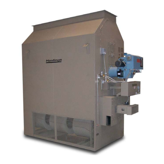
D. EQUIPMENT DESCRIPTION The Counterflo heater is a rugged industrial grade space heater. Models are available for vertical upright mounting indoors, or outdoors, and horizontal mounting for indoor floors, ceiling suspension or rooftops. 1. Cabinet and Frame Rugged channel iron frame and all cabinet surfaces are painted with heat and corrosion resistant industrial enamel. - Page 6 5. Control System The standard On-Off control system is obtained with a single pole, single throw thermostat that closes upon a temperature drop below setpoint. Fan operation is intermittent. A detailed sequence of operation for standard gas-fired heaters is provided later in this manual.
-
Page 7: Section Ii. - Installation Procedure
SECTION II. – INSTALLATION PROCEDURE This equipment shall be installed and wired in accordance with regulations of the National Board of Fire Underwriters, National Electric Code, and local governing bodies. following recommendations are not intended to supplant any requirements of federal, state, or local codes having jurisdiction. -
Page 8: Combustion Air Openings
The following recommendations are not intended to supplant requirements of federal, state or local codes having jurisdiction. All local authorities having jurisdiction should be consulted before the installation is made. The heater should be installed in accordance with the standard of the National Board of Fire Underwriters for the class and all wiring connections must conform to the National Electric Code. - Page 9 Type DIMENSIONS IN INCHES Qty. MODEL Hood/ Nozzles Nozzle 40/55 50¾ 5/16 104½ 16¾ 15¼ 60/85 94⅝ 39 ⅛ 61⅛ 22¾ 49⅝ 1½ 5/16 114⅛ 100/125 98⅛ 44⅝ 70⅝ 21⅝ 51¾ 5/16 118⅛ 150/175 55⅛ 91⅛ 25¼ 5/16 132½ 22½ 200/225/250 130¾...
-
Page 10: Location Of Accessories
Locate the Counterflo heater exactly level. Special attention should be given to the exhaust duct connections, electrical power and control hookup points, and fuel connection points. This information should be cross-checked with the position of support beams and stand pipes to insure that clearance dimensions coincide with those of the unit. - Page 11 and 3” depending on the Counterflo model and type of gas. On gas systems, vent pressure regulator(s) and vent valve (if included with unit) to outside of building. With vent pipe outside, install a proper vent cap and/or screen to prevent entrance of foreign material and plugging.
- Page 12 Furnished and Installed by Others Furnished By Factory, Installed By Others Factory Furnished And Installed ITEM DESCRIPTION Drip Leg Main Gas High Pressure Hand Shut-Off Valve (If Required) Main Gas High Pressure Regulator (If Required) Vent Line Thru Roof To Outside Atmosphere Main Gas Hand Shut-Off Valve Main Gas Pressure Regulator Safety Shut-Off Valve...
- Page 13 Furnished and Installed by Others Furnished By Factory, Installed By Others Factory Furnished And Installed ITEM DESCRIPTION Oil Hand Shut-Off Valve Oil Filter Oil Safety Valve Oil Pressure Gauge Burner Oil Pump Main Oil Solenoid Valve Oil Nozzle Oil Cylinder By-Pass Oil Solenoid Valve By-Pass Pressure Regulator Check Valve...
- Page 14 -11-...
- Page 15 Figure 6 – Typical Light Oil Piping Suction System - - Two-Pipe Method -12-...
-
Page 16: Exhaust Duct Connection
G. EXHAUST DUCT CONNECTION Installation of exhaust stack must comply with regulations of the National Board of Fire Underwriters and local governing bodies. The exhaust stack, exhaust stack connector, exhaust stack support and miscellaneous items related to the exhaust stack are to be supplied and installed by others. Exhaust stack located inside the building must be positive pressure vent. - Page 17 MODEL 40/55 4” 8” 8” 13” 13” 18” 18” 6-1/2” 3-3/4” 69 –1/4” 16” 7-3/8” 60/85 5” 10” 10” 16” 18” 22” 26” 7 5/8” 4-3/8” 72-1/16” 20” 8-5/16” 100/125 5”/6” 10”/12” 10”/12” 16”/18” 18”/20” 22”/24” 26”/28” 9-1/4” 5-1/4” 73-1/16” 20”/24”...
- Page 18 -15-...
-
Page 19: Section Iv. - Start-Up
3. Check all electrical connections in the main control panel. 4. Check that all fuses are installed and that fuse sizing agrees with the unit bill of material. 5. Check to see if all gas, oil, or gas/oil connections are tight and that all joints have been properly lubricated. - Page 20 d. Combustion air and exhaust air proving switches are factory set for 0.2” to 0.4” W.C. 2. Open pilot gas cock and purge air from gas line through plugged tee in pilot line. Caution: Use a lighted torch to ignite the gas as air is purged from the pilot gas line. Do not depend on sensing the odor of gas to determine if the gas line is purged.
- Page 21 WARNING: Never stand within the swing radius of the access door when making flame observations through the peephole. Proper flame travel within the stainless steel combustion chamber differs from the pattern usually desired for a refractory lined furnace. Never adjust the burner to produce a short “bushy”...
- Page 22 -19-...
- Page 23 CHAMBER BREECHING PRESSURE PRESSURE FULL RATED COUNTERFLO (Neg. “W.C.) (Pos. “W.C.) EXHAUSTER RPM MODEL # MBH OUTPUT 1400 1400 .055 .033 1500 1500 1300 1300 2030 2030 1000 1500 1500 1.00 1250 1900 2000 1.10 1500 1640 1640 1.10 1.10 1750 1875 1875...
- Page 24 has yellow or yellow tip appearance, open combustion air louver wider until flame appears short and hard. Adjust gas pressure regulator on burner to the unit name plate operating pressure rating while firing with the manual gas cock in the wide open position. Read gas meter serving burner, input should be approximately that stated on the burner name plate.
- Page 25 -22-...
-
Page 26: Section V. - Maintenance Schedule And Lubrication Requirements
13. Referring to Figure 12, the typical sequence of operation for an On-Off gas-fired unit is as follows: a. Closing fused disconnect switch (FD) will energize 115 volt control circuit through control transformer (T2). b. The On-Off burner switch (XB) on the master control panel will operate the blower. Unit burner operation is controlled by the On-Off thermostat (RT). -
Page 27: Lubrication Instructions
Yearly 1. Remove rear access plate and clean out economizer tubes. (Place receptacle to collect soot as the swirlers are pulled out. Do not operate fans while access plate is off as considerable soot may be blown into surrounding area.) Be sure gasket is properly seated when replacing the access plate. -
Page 28: Testing Of Controls & Safety Devices
C. TESTING OF CONTROLS AND SAFETY DEVICES The Safety and Operating Controls shall be periodically tested to maintain the safe operation of the furnace. Items to be tested include; High Limit, Gas/Oil Safety Shut-off Valves, Thermostats, Air Proving Switches and Flame Safeguards. Thermostat: 1. -
Page 29: Section Vi. - Troubleshooting
3. Burner should light and when discharge temperature reaches the limit set point, the burner should shut down. This should occur within 10 minutes maximum. 4. Reset Motor Overload Relay and remove jumpers on Air Proving Switch. 5. Refer to the High Limit Manufacturers’ Installation and Maintenance Manual for further information. -
Page 30: Troubleshooting Oil-Fired Units
100# pressure. Field service, other than pressure adjustment and strainer cleaning, is not recommended. The pump can be readily detached from the mounting base and motor coupling for replacement on an exchange basis. Contact Hastings HVAC Service Department for details. -27-... - Page 31 -28-...
-
Page 32: General Troubleshooting Tips
The pump is normally factory-set for a two-pipe system as described in Figure 14B; see figure 14A for single-pipe system details. CAUTION: Where a single-pipe system is used, the bottom of the tank must be above the pump. 1. Procedure for two-pipe installation: a. - Page 33 1. Rota-Roll Gears 2. Cutoff Valve 3. Positive Strainer 4. Leakproof Diaphragm Type Shaft Seal 5. Anti-hum Device 6. Large Shaft Bearing 7. Body 8. Bleed Valve -30-...
- Page 34 At this point, all common causes of trouble have been covered and one or more of the remedies suggested should have corrected the malfunction. However, if the unit still does not function properly, notify the nearest Hastings HVAC Field Service Engineer at 1- 800-228-4243 or 4270.
- Page 35 STANDARD B139 FOR RECOMMENDED INSTALLATION PRACTICE; OIL-FIRED APPLIANCES SHALL BE CONNECTED TO FLUES HAVING SUFFICIENT DRAFT AT ALL TIMES TO ENSURE SAFE AND PROPER OPERATION OF THE APPLIANCE. For Service Parts and Assistance call: Hastings HVAC Service Co. at (800) 228-4243 or 4270...
- Page 36 PO Box 669 3606 Yost Avenue Hastings, NE 68902- 0669 Phone (402) 463-9821 Fax (402) 462-8006 sales@hastingshvac.com www.hastingshvac.com...
Need help?
Do you have a question about the COUNTERFLO CF SERIES and is the answer not in the manual?
Questions and answers