
Related Manuals for Hastings AEROFLO AFX Series

Summary of Contents for Hastings AEROFLO AFX Series
- Page 1 ISAFX-1 April 2014 Supersedes March 2012 Installation and Service Manual AEROFLO AFX SERIES HEATERS GAS FIRING Notice Read These Instructions before Installation...
-
Page 2: Table Of Contents
TABLE OF CONTENTS Page Section I. – General Information ………………………………………… Purpose ……………………………………………………… Shipping ……………………………………………………… Storage……………………………………………………….. Optional Factory Service …………………………………… Equipment Description …………………………………….. Section II. – Installation Procedure ………………………………………. Handling the Equipment ……………………………………. Positioning the Unit ……………………………………….. Location of accessories …………………………………….. Electrical connections ………………………………………. -
Page 3: General Information
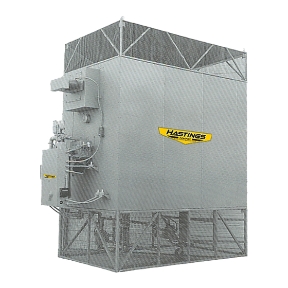
The purpose of this manual is to present a guide for proper installation, maintenance, and operation of Aeroflo AFX Series heaters, and to supplement, but not to replace, the services of qualified field service personnel to supervise the initial start-up and adjustment of the Aeroflo unit. - Page 4 Minimum standard entering gas pressure is 4 ounces. 4. Fuel and Electric Controls Standard components for Aeroflo AFX Series heaters include a Nema 1 control box with electronic flame safeguard system with ignition transformer, motor starter, control transformer, high temperature limit switch, air flow switch, and a gas electrical control system.
-
Page 5: Installation Procedure
SECTION II. – INSTALLATION PROCEDURE This equipment shall be installed and wired in accordance with regulations of the National Board of Fire Underwriters, National Electric Code, and local governing bodies. The following recommendations are not intended to supplant any requirements of federal, state, or local codes having jurisdiction. - Page 6 Note: Over-all final dimensions may differ from those stated in "Dimensions" table.
-
Page 7: Location Of Accessories
C. LOCATION OF ACCESSORIES Where applicable, standard or optional accessories will be placed inside the fan section of the unit for shipment, and must be removed and installed by the mechanical or electrical contractor. D. ELECTRICAL CONNECTIONS All wiring must comply with all applicable local, state, provincial, and national electric codes. - Page 8 Length of GAS FLOW CAPACITY (CFH) Pipe Iron Pipe Size (IPS) Inches (Equiv. Ft.) 1-1/4 1-1/2 1220 2480 6500 13880 38700 79000 1780 4700 9700 27370 55850 1470 3900 7900 23350 45600 1290 3450 6800 19330 39500 1120 3000 6000 17310 35300 1000 2700...
-
Page 10: Exhaust Duct Connection
EXHAUST DUCT CONNECTION Installation of exhaust stack must comply with regulations of the National Board of Fire Underwriters and local governing bodies. The exhaust stack, exhaust stack connector, exhaust stack support and miscellaneous items related to the exhaust stack are to be supplied and installed by others. - Page 11 OPTIONAL REMOTE CONTROL PANEL INSTALLATION Refer to Figure 5 for guidelines. All writing must comply with applicable electric codes. Align box with spirit level. If box is to be surface mounted, three (3) mounting holes in back of box are recommended, one in each top corner and one at bottom center.
-
Page 14: Pre-Start Inspection
SECTION III. – PRE-START INSPECTION A pre-start inspection is extremely important and should be completed with greatest attention given to detail. This will insure against possible unit damage on start-up and will save valuable analysis time in the event malfunctions occur on start-up and check-out. A. - Page 15 cause excessive load on bearings. After initial start, allow the belts a few days running time to become seated in pulley grooves, then readjust as necessary. Do not roll belts over grooves or sheaves as this will result in permanent belt damage.
- Page 18 1.45 272/284 2750 1850 1.60 3000 1850 1.75 3250 1850 1.90 3500 1850 2.00 4500 1850 1.65 Note: Values shown are those obtained when firing at full rated output. Figure 8 – Typical Draft Conditions for Aeroflo AFX Series Heaters...
- Page 19 10. Burner Start-up Open the air louver on the air inlet to approximately the one-half open position. Open the manual gas valve slowly, burner will ignite. Open valve until gas pressure on the gauge is approximately 4 ounces. (See spec plate for factory differential pressure settings.
- Page 20 Variable________ As Read____________ Exhauster Design Speed ____________ Drive Fixed_________ Variable________ As Read____________ BURNER OPERATION MFG. HASTINGS MAXON OTHER _____________ MODEL ____________________ ________________ _______________ FUEL TYPE NG or LP DESIGN INLET PRESSURE _____________ “ W.C./PSI AS TESTED __________ : W.C./PSI BURNER (High Fire) OPERATING DIFF. PRESSURE (7” W.C. MAX) AS TESTED _______” W.C.
- Page 21 This unit has been tested and inspected to insure that: (1) Fabrication, wiring, quality and location of all materials agree with Hastings HVAC Standard. (2) Bearings, sheaves, belts, and motors have proper alignment, lubrication and adjustment. (3) Controls, valves and programmers have proper sequence of operation and setting.
-
Page 22: Procedure
SECTION V. – MAINTENANCE SCHEDULE AND LUBRICATION REQUIREMENTS A. MAINTENANCE SCHEDULE – Caution: Always wear proper protective gear with face shield while operating these units. Weekly 1. Check that fan belts are tight and sheaves are lined up. 2. Check gas pressure at burner. Monthly 1. -
Page 23: Lubrication Instructions
B. LUBRICATION INSTRUCTIONS Item Manufacturer Bearing Type Recommendation All 3 phase fan motors (1 HP U.S. or equal Single row ball Note #2 to 100 HP) ODP or TEFC bearings Fractional HP exhauster Century, G.E., Sealed ball Note #1 motors, single phase, ODP or or equal bearings TEFC... -
Page 24: General Troubleshooting Tips
At this point, all common causes of trouble have been covered and one or more of the remedies suggested should have corrected the malfunction. However, if the unit still does not function properly, notify the nearest Hastings HVAC, Inc. Field Service Engineer.
Need help?
Do you have a question about the AEROFLO AFX Series and is the answer not in the manual?
Questions and answers