
Related Manuals for Moorwood Vulcan MLE60R-F-S

Summary of Contents for Moorwood Vulcan MLE60R-F-S
-
Page 1: Parts List
MEDIUM DUTY ELECTRIC GENERAL PURPOSE RANGE, OVENS & BOILING TABLES OWNER’S MANUAL Click here for Parts List Manual Part No: 930158-01 MD Electric Range - 1 – Manual Rev No: 1... -
Page 2: Manual Part No
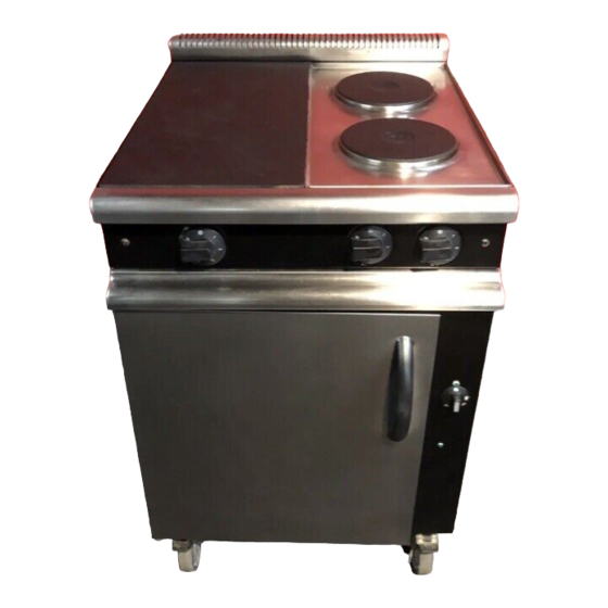
Model No. Product Description Rev. Date M-Line Ranges MLE60R-F-S 600 Range - 2 Solid Plates 14/08/00 MLE60R-F-RS 600 Range - 1 Solid/2 Rings 14/08/00 MLE90R-F-S 900 Range - 2 Solid Plates 14/08/00 MLE90R-F-RS 900 Range - 2 Solid/2 Rings 14/08/00... -
Page 3: Table Of Contents
INDEX Page Cover Sheet: Revision Sheet: Index: Introduction: 4 & 5 General Introduction Important Note Specification: 6 - 18 Electric Supply/Connection 6 & 7 Dimensions 7 - 11 Wiring Diagrams 12 - 18 Installation: 19 - 22 Important Note Positioning Electrical Connection Checking &... -
Page 4: Introduction
INTRODUCTION This manual contains all the required information to ensure that your new appliance is installed correctly and that you have all the information necessary to identify and order spare parts. It also contains comprehensive instructions for the user and for cleaning the appliance. To maintain peak performance, it is recommended that the appliance be regularly serviced and that when ordering spare parts, reference be made to the appropriate list quoting the Part No. -
Page 5: Introduction
Introduction (cont.) Important Before installing any item please refer to the installation instructions. We recommend that all servicing other than routine cleaning be carried out by our authorised service agents and will accept no responsibility for work carried out by other persons. For satisfactory operation parts of catering equipment become hot. -
Page 6: Specification
Total - 15.5kW Weight - 127kg 600 Range - 2 Solid Plates - (MLE60R-F-S) Supply- 400V, 50Hz, 3 Phase (alternative 240V, 50Hz, 1 Phase) Phase Loading - L1 - 4.0kW, L2 - 3.0kW, L3 - 3.0kW (1 Phase - 10.0kW) Oven - 4.0kW... - Page 7 Specification (Cont.) 900 Boiling Table - 2 Solid Plates, 2 Round Hotplates - (MLE90BT-F-RS) Supply - 400V, 50Hz, 3 Phase (alternative 240V, 50Hz, 1 Phase) Phase Loading- L1 - 3.0kW, L2 - 3.0kW, L3 - 3.5kW (1 Phase - 9.5kW) Solid Hotplate- 2 x 3.0kW Round Hotplate- Front - 1.5kW, Rear - 2.0kW Total...
- Page 8 Specification (cont.) Wiring Variations to Back-Outer Terminal Block 927883-01 Manual Part No: 930158-01 MD Electric Range - 8 – Manual Rev No: 1...
- Page 9 Specification (cont.) Dimensions – MLE90R-F-S, MLE90R-F-RS, MLE90BT-F-S & MLE90BT-F-RS Manual Part No: 930158-01 MD Electric Range - 9 – Manual Rev No: 1...
- Page 10 Specification (cont.) Dimensions – MLST90EGP-F Manual Part No: 930158-01 MD Electric Range - 10 – Manual Rev No: 1...
- Page 11 Specification (cont.) Dimensions – MLE60R-F-S & MLE60R-F-RS Manual Part No: 930158-01 MD Electric Range - 11 – Manual Rev No: 1...
-
Page 12: Wiring Diagrams – Mle90R-F-S
Specification (cont.) Wiring Diagrams – MLE90R-F-S Manual Part No: 930158-01 MD Electric Range - 12 – Manual Rev No: 1... - Page 13 Specification (cont.) Wiring Diagrams - MLE90R-F-RS Manual Part No: 930158-01 MD Electric Range - 13 – Manual Rev No: 1...
- Page 14 Specification (cont.) Wiring Diagrams – MLE60R-F-S Manual Part No: 930158-01 MD Electric Range - 14 – Manual Rev No: 1...
- Page 15 Specification (cont.) Wiring Diagrams – MLE60R-F-RS Manual Part No: 930158-01 MD Electric Range - 15 – Manual Rev No: 1...
- Page 16 Specification (cont.) Wiring Diagrams – MLE90BT-F-S Manual Part No: 930158-01 MD Electric Range - 16 – Manual Rev No: 1...
- Page 17 Specification (cont.) Wiring Diagrams – MLE90BT-F-RS Manual Part No: 930158-01 MD Electric Range - 17 – Manual Rev No: 1...
-
Page 18: Specification
Specification (cont.) Wiring Diagrams – MLST90EGP-F Manual Part No: 930158-01 MD Electric Range - 18 – Manual Rev No: 1... -
Page 19: Installation
INSTALLATION Important MUST This appliance be installed by a competent person in accordance with these and any other relevant regulations. MUST The installation wiring comply with the latest I.E.E. Regulations. WARNING: THIS APPLIANCE MUST BE ELECTRICALLY EARTHED Before Installation Before commencing installation, remove all packaging materials from the appliance. It is suggested that any protective film adhering to the stainless steel panels should be left on until installation is completed. - Page 20 Installation (cont.) Electric Connection The connection should be made in electrical conduit, via a fused mains isolator on the wall adjacent to MUST the appliance. The final connection be in flexible conduit so that the connections can be made at the rear of the appliance before it is moved into position.
-
Page 21: Grill Over Range
Installation (cont.) 900 Grill over Range Screw the two grill supports (A) to the rear of the range using the 6 screws provided. The nuts are already in place on the back of the range. Place the grill on the 2 grill supports, ensuring the front edge of the grill supports locate inside the returned flange of the grill lower panel (D). -
Page 22: Installation
Installation (cont.) 600 Grill over Range Screw the 2 grill supports (A) to the rear of the range using the 6 screws provided. The nuts are already in place on the back of the range. Place shelf onto support (A) ensuring support tab (D) locates inside front edge of shelf. Secure shelf to supports using 2 screws. -
Page 23: Important Note
USERS INSTRUCTIONS Important Note! MUST The attention of the user is drawn to the fact that this appliance be installed by a competent I.E.E. REGULATIONS. person in accordance with the latest See also the section of this manual referring to Cleaning and General Maintenance. Safety Note This appliance is intended for professional use and shall only be used by qualified personnel. - Page 24 Users Instructions (cont.) Controls An isolating switch will have been fitted adjacent to the appliance to enable the power to be switched off when servicing work is being carried out. The isolating switch should also be switched off when the appliance is not going to be used for a long period, e.g.
-
Page 25: Cleaning
Users Instructions (cont.) Oven The 900mm oven has three elements (each of 2.0kW), in the sides and rear of the oven cavity. The 600mm oven has two elements (each of 2.0kW), in the sides of the oven cavity. There are six shelf positions on the shelf hangers and two shelves are provided as standard. The shelves, shelf hangers and vitreous enamelled oven sides and rear can all be removed for cleaning. - Page 26 Users Instructions (cont.) Cleaning (Cont.) Clean stainless steel with soap and hot water or a mild detergent solution. Rinse and dry thoroughly. DO NOT USE CAUSTIC OR ABRASIVE CLEANERS, DO NOT USE ABRASIVE PADS BEFORE Vitreous enamelled surfaces should be wiped clean of grease and spillage they are burnt on.
-
Page 27: User Instructions
Users Instructions (cont.) General Maintenance and Care (Cont.) WE RECOMMEND THAT ALL EQUIPMENT IS SERVICED AT LEAST ONCE A YEAR, BUT MAY BE AS FREQUENT AS 6 MONTHS OR LESS IF CONTROLS FAIL TO OPERATE FREELY. ALL WORK MUST BE CARRIED OUT BY A QUALIFIED SERVICE ENGINEER. -
Page 28: Operation
SERVICE AND MAINTENANCE ENSURE THAT THE ELECTRICITY SUPPLY TO THE APPLIANCE HAS BEEN TURNED OFF BEFORE DISMANTLING ANY COMPONENTS. MUST Maintenance only be carried out by a competent person. Routine Maintenance Procedures: Turn the electricity supply to the range and check that the green neon is alight. Turn the oven thermostat and check that the oven amber neon is working. -
Page 29: Fault Finding
Service and Maintenance Instructions (cont.) Fault Finding Fault Possible Cause Remedy Mains Isolator ON. a) Neon lamp faulty. Replace. Replace after checking all Green Neon OFF. b) External fuse blown. possible reasons for failure. NO HEAT IN OVEN Amber Neon stays ON. Contactor not working. -
Page 30: Service & Maintenance
Service and Maintenance Instructions (cont.) To Change A Thermostat Remove the RH inner oven side panel. Remove the vertical control panel (one screw on underside - two screws on top). Unclip thermostat phial and feed back through side panel into void. Unfasten thermostat from bracket (one nut) and disconnect wires. -
Page 31: Instructions
Service and Maintenance Instructions (cont.) To Check A Rectangular Hotplate Element (cont.) To check a hotplate to ensure that the switches and elements are wired correctly:- With the horizontal control panel removed, pull forward the neon bracket and switch plate to expose the 6 heat switch/es. -
Page 32: Spare Parts
SPARE PARTS LIST Part Number Description Quantity 930094-01 Oven Thermostat 924486-01 Six Heat Switch 2, 3 or 4 19000010 Contactor 922698-01 Green Neon 922698-02 Amber Neon 924387-01 Oven Element 2 or 3 924443-S1 Solid Hotplate Complete (Spares Kit) 1, 2 or 3 924427-01 Solid Hotplate Element 4/Plate... - Page 33 VISCOUNT CATERING LIMITED The Company offer twelve months warranty with each new piece of equipment subject to our normal conditions of sale and will undertake responsibility for warranty subject to the additional following conditions. Notice of the defect/damage is given within 48 hours of breakdown or in the case of damage four days from the date of despatch and the manufacturer given adequate opportunity to examine the goods in order that appropriate action can be taken.
-
Page 34: Manual Part No: 930158-01 Md Electric Range
Manual Part No: 930158-01 MD Electric Range - 34 – Manual Rev No: 1...
Need help?
Do you have a question about the MLE60R-F-S and is the answer not in the manual?
Questions and answers