
Related Manuals for Gene Cafe CBR-101A

Summary of Contents for Gene Cafe CBR-101A
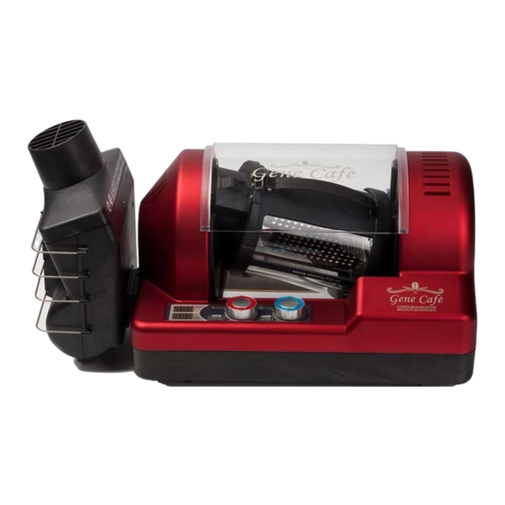
- Page 1 Service Manual (Rev. 01) COFFEE BEAN ROASTE R MODEL CBR-101 A INNOVATIVE OFF - AXIS ROTATION • To ensure safe, trouble-free operation, please carefully read this manual • Warranty information contained in this manual. Do not discard.
-
Page 2: Safety Cover
Gene Cafe Replacement Instructions REV. 01 _ 070315 Model : Gene Café (CBR-101) SAFETY COVER Requirements Picture Instruction Process ● Make sure that unpug the power cord before the assembly and disassembly. ● After open the safety cover, lift the chamber maked in this picture. -
Page 3: Top Cabinet
Picture Instruction Process ● Unscrew them indicated in the picture. ●Remove the base panel to use a tool indicated in the picture. Disassembly ● Pull out the side cover as indicated in the picture by green arrow. Causion) The process by reassembling, make sure the direction of side cover. - Page 4 ● Lift the top cabinet with both hand as indicated here by the green arrow. ● Remove the connector with hands. in this picture. Disassembly TOP CABINET ● To assembly the top cabinet, Hold the top cabinet with hand maked in the picture, and the Control Lead Wire BOSS to locate between transformer and Boss.
- Page 5 DAMPER OUT ASS'Y Requirements Picture Instruction Process ● In the main PCB, remove the "Temp Sen(1)" by long nose. ● Rescrew them as indicated in this picture and then, Remove the bottom cabinet as lift the damper out Ass'y. Disassembly ●...
- Page 6 by long nose. ● Rescrew them as indicated in this picture. Disassembly ● With minus driver, Remove the motor gear from motor shaft as indicated by this picture. ● To reassembly, Damper out ass'y apply by silicone as indicated by this picture. ●...
- Page 7 ●Lead wire of Temp sensor(2) have to through heater box ass'y and bottom cabinet boss as indicated by this picture. opposite operation of disassembly. Assembly HEAT BOX ASS'Y Requirements Picture Instruction Process ● In the Power PCB, remove the connection of heater by long nose.
- Page 8 ● To assembly, Insert as indicated by this picture. ● Screw the bolt as indicated by this picture opposite operation of disassembly. Assembly REED SENSOR PCB Requirements Picture Instruction Process ● In the main PCB, remove the "REED SENS" by long nose. ●...
- Page 9 Disassembly ● To assembly, make sure that, the REED SENSOR located left side of PCB. opposite operation of disassembly. Assembly Requirements Picture Instruction Process ● In the main PCB, remove the "FAN" connector by long nose. ● Rescrew them as indicated in this picture and then, Remove the FAN as lift from bottom cabinet.
-
Page 10: Power Cord
opposite operation of disassembly. Assembly POWER CORD Requirements Picture Instruction Process ● Remove the Twe connector as indicated in this picture from the main PCB and FUSE HOLDER. ● Rescrew them as indicated in this picture Disassembly ● With Cord Pusher, Push the cord push and then as indicate by the arrow. - Page 11 TRANSFORMER Requirements Picture Instruction Process ● Rescrew them as indicated in this picture. ● Remove the connector as indicated in small picture by long nose. Disassembly “A” ● Cordinated the Led wire as indicated in this picture. opposite operation of disassembly. Assembly MAIN PCB Requirements...
- Page 12 by hands. ● Rescrew them as indicated in this picture . Disassembly ● To remove the PCB from Bottom cabinet, make sure indicated by green arrow. opposite operation of disassembly. Assembly POWER PCB Requirements Picture Instruction Process ● In the Power PCB, remove all of connector as in this picture.
-
Page 13: Control Pcb
Disassembly ● Rescrew them as indicated in this picture. opposite operation of disassembly. Assembly CONTROL PCB Requirements Picture Instruction Process ● Rescrew them as indicated in this picture and remove from Top cabinet. ● To Reassembly, Make sure the location of Control as indicated in this picture. -
Page 14: Fuse/Fuse Holder
● Remove the Knob by minus driver to easier. Disassembly ● Make sure the shape of Knob and Shaft to as indicated in this picture. opposite operation of disassembly. Assembly FUSE/FUSE HOLDER Requirements Picture Instruction Process ● With minus driver, remove the Cap as indicated by green arrow. -
Page 15: Power Panel
● Rescrew the Fuse holder as indicated by green arrow, and then push that to remove. opposite operation of disassembly. Assembly POWER PANEL Requirements Picture Instruction Process ● To remove, Push the Power panel as indicated in this picture. Disassembly opposite operation of disassembly. - Page 16 ● Remove the CPU by CPU extractor as indicated in small picture. Disassembly ●To reassembly, make sure the location of CPU as in this picture. Assembly opposite operation of disassembly. MOTOR BRACKET ASS'Y(L) Requirements Picture Instruction Process ● Remove the Reed sensor and connector of Motor Main PCB as indicated in this picture.
- Page 17 ●To Reassembly, make sure to match Boss of with hole of Bracket as indicated in this picture. opposite operation of disassembly. Assembly MOTOR BRACKET ASS'Y (R ) Requirements Picture Instruction Process ● To remove, rescrew them as indicated in this picture. by long nose.
- Page 18 ● Rescrew them as indicated in this picture. Disassembly ● To reassembly., make sure the shape of them to as indicated in this picture. opposite operation of disassembly. Assembly CONNECTING SHAFT ASS'Y Requirements Picture Instruction Process ● After remove the Motor Bracket Ass'y, remove the connecting Shaft Ass'y.
-
Page 19: Bottom Cabinet
Disassembly short ● Before the reassembly, check the Bearing as in this picture. opposite operation of disassembly. Assembly FUNCTION PLATE Requirements Picture Instruction Process ●To remove the Function plate, Push that as this picture. Disassembly opposite operation of disassembly. Assembly BOTTOM CABINET Requirements Picture... - Page 20 Disassembly DUST NET Requirements Picture Instruction Process ● Remove the Dust net from bottom cabinet by long as indicated in this picture. Disassembly opposite operation of disassembly. Assembly SEPARATOR Requirements Picture Instruction Process ● With a driver, remove the separator as indicated by green arrow.
- Page 21 opposite operation of disassembly. Assembly FOOT PAD Requirements Picture Instruction Process ● look at the Foot Pad as indicated in this picture. Disassembly ● With minus driver, Remove the Foot Pad as indicated in this picture. opposite operation of disassembly. Assembly how to clean a dust net and chaff collector Requirements...
-
Page 22: How To Clean The Fan Filter
● Remove the cap from Chaff collector,and then clean inside of collector by vaccum as maked in this photo. ● possible to clean as water, and please make sure to complete dry a chaff collector for a safety. Disassembly ● clean the dust net as any brush HOW TO CLEAN THE FAN FILTER Requirements Picture... - Page 23 ● possible to clean as vaccum or others. Remark GS-DOC-0704-CS Innovative off-axis rotation Genesis Co., Ltd.
Need help?
Do you have a question about the CBR-101A and is the answer not in the manual?
Questions and answers