Advertisement
MICROPROCESSOR CONTROL (CPU)
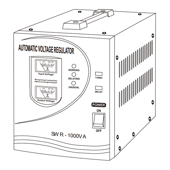
AUTOMATIC VOLTAGE REGULATOR
HIGH & LOW VOLTAGE PROTECTION
A U T O M A T IC V O LT A G E R E G U L A T O R
Mic rop roc ess or Co
Hig h & Lo w Vol tag
Instruction Manual
Please read user manual carefully before use.
In pu t Vo lta ge
ntr ol( CP U)
e Pro tec tio n
O ut pu t Vo lt ag
e
Advertisement
Table of Contents

Subscribe to Our Youtube Channel
Summary of Contents for paco SWR-3000VA
- Page 1 MICROPROCESSOR CONTROL (CPU) AUTOMATIC VOLTAGE REGULATOR HIGH & LOW VOLTAGE PROTECTION A U T O M A T IC V O LT A G E R E G U L A T O R In pu t Vo lta ge Mic rop roc ess or Co ntr ol( CP U) Hig h &...
- Page 2 1. FEATURES Microprocessor Control (CPU) Wide Range Voltage Regulation Automatically Executes Protection, When Protection Finished, Goes Off. High Voltage Protection: Yes Low Voltage Protection: Yes Circuit Protection: Circuit Breaker High Temperature Protection: Yes NOTE: Not equipped overheating Protection in standard configuration, users should notify manufacturer and take special order if this function is required.
- Page 3 FIG 2 Rear Panel: 1000VA-2000VA Front Panel: 1000VA-2000VA WORKING INDICATOR DELAYING INDICATOR UNUSUAL INDICATOR AU TO MA TIC VO LT AG E RE GU LA TO R INPUT VOLTAGE METER Inp ut Vol tag e Micr opro cess or Con OUTPUT VOLTAGE trol( CPU ) High &...
- Page 4 FIG 4 Rear Panel: 8KVA-10KVA Front Panel: 8KVA-10KVA WORKING INDICATOR DELAYING INDICATOR UNUSUAL INDICATOR AU TO MA TIC VO LT AG E RE GU LA TO R INPUT VOLTAGE METER OUTPUT VOLTAGE Micr opro cess or Con trol( CPU ) High &...
- Page 5 3. INDICATING SIGN WHEN THE GREEN INDICATOR IS LIGHTING. THE REGULATOR IS WORKING. WORKING WHEN ORANGE INDICATOR IS FLASHING EVERY ONE SECOND, THE SYSTEM IS TURNING INTO DELAYING STATE, AND THE REGULATOR HAS NO OUTPUT. AFTER DELAY, ORANGE INDICATOR WILL DELAYING EXTINGUISH AND THE REGULATOR RESUME OUTPUT.
-
Page 6: Led Indicator Illustration
4. LED INDICATOR ILLUSTRATION LED Indicator Illustration CONDITION WORKING-G DELAYING-Y UNUSUAL-R Power Off Working Delay State Output high voltage protection Output low voltage protection High temperature protection NOTE: : CONTINUOUSLY ILLUMINATE : FLASH : EXTINGUISH NOTE: Indication for overheating is not equipped in standard configuration. - Page 7 When DELAY OFF, the system is entering into countdown position, delay time is 6 seconds. When DELAY ON, the system is entering into countdown position, delay time is 120 seconds. When TURBO ON, input voltage range is the rated input voltage labeled on the unit.
-
Page 8: Thermal Protection
6. LOW & HIGH VOLTAGE PROTECTION When output voltage is lower or higher than labeled voltage, AVR will turn into self-protection state automatically ,the UNUSUAL RED indicator flashes every one second and output voltage will be cut off. When output voltage comply with labeled voltage, AVR will go into automatic recovering state, the UNUSUAL RED indicator extinguishes. -
Page 9: Grounding Connection
9. GROUNDING CONNECTION WARNING: BEFORE USING THIS AUTOMATIC VOLTAGE REGULATOR YOU MUST PROVIDE A GROUND CONNECTION TO THE AUTOMATIC VOLTAGE REGULATOR. On the rear panel of the automatic voltage regulator is a terminal fitted with a nut. This terminal is connected to the case of the automatic voltage regulator and also to the earth terminal of the AC output socket. - Page 10 In a stationary land based installation, the earth terminal should be connected to a metal earthing stake driven into the ground to a depth of 1.2m or more. Model: 3KVA, 5KVA Output Input Output GROUND TERMINAL Model: 8KVA, 10KVA GROUND TERMINAL Input Output NOTE:...
-
Page 11: Maintenance
10.CAUTION In case of trouble with the AC output, e.g.short-circuit, overload, etc... the protection circuit will automatically cut off the output. In such cases: (A) switch off the power at once (B) disconnect all units (C) check the connected devices (D) use the unit again unless the problems concerning the connected devices have been solved When in use for a prolonged period of time, the AC output may suddenly be... - Page 12 12. EXPERT OF PROTECTOR FOR Make sure that the to tal laden power does not exceed the listed maximum output power of the regulator. Be sure to connect the ground point to the ground for your safty. Expert of Protector For:...
-
Page 13: Specification
13. SPECIFICATION P/No. SWR-500VA SWR-1000VA SWR-1500VA SWR-2000VA Input 100-260V~ 120-260V 140-260V 160-260V~ 80-140V~ Voltage Output 220V 230V 240V 110V 115V Voltage Output 500VA 1000VA 1500VA 2000VA Power Frequency 50/60Hz Output +/-10% Precision High Voltage Circuit Protection Protection Voltage Circuit Protection Protection High Output... - Page 14 14. SPECIFICATION P/No. SWR-3000VA SWR-5000VA SWR-8KVA SWR-10KVA Input 100-260V~ 120-260V 140-260V 160-260V~ 80-140V~ Voltage Output 220V 230V 240V 110V 115V Voltage Output 3000VA 5000VA 8000VA 10000VA Power Frequency 50/60Hz Output +/-10% Precision High Voltage Circuit Protection Protection Voltage Circuit Protection...
- Page 15 CAUTION Avoid overloading Do not use the regulator beyond its maximum power. When connected to any appliance with built-in motor compressor, the starting power is generally several times of the appliance's listed power rating. Make sure that the total starting power capacity of all connected appliance does not exceed the listed maximum output power of the regulator.
Need help?
Do you have a question about the SWR-3000VA and is the answer not in the manual?
Questions and answers