Table of Contents
Advertisement
Quick Links
Advertisement
Table of Contents

Related Manuals for Romantis Satellite Communications UHP-1000

Summary of Contents for Romantis Satellite Communications UHP-1000
- Page 1 SATELLITE ROUTER UHP-1000 USER MANUAL SOFTWARE RELEASE 3.0 MAY 2013...
-
Page 2: Table Of Contents
UHP Software 3.0 User Manual Table of contents 1. Glossary 2. Hardware overview and functions 2.1 Interfaces and controls 3. State analysis 3.1 Front panel indication 3.2 Faults 3.3 Events 4. UHP access for configuration 4.1 USB interface 4.2 Telnet interface 4.3 Default configuration 5. - Page 3 UHP Software 3.0 User Manual 12.5.3 Redundancy 13. System 13.1 Overview 13.2 Interfaces 13.3 Ethernet statistics 13.4 Demodulator statistics 13.5 Modulator statistics 13.6 Time-related 13.7 User access 13.8 Flash/Boot 13.9 Save/Load 14. Maintenance 14.1 Support information 14.2 Pointing 14.3 Network Command 14.4 Traffic generator 14.5 Reboot Document version 1.0, May 2013...
-
Page 4: Glossary
UHP Software 3.0 User Manual 1. Glossary 16APSK 16 Amplitude and Phase-shift keying or Asymmetric Phase-shift keying, (APSK), is a digital modulation scheme that conveys data by changing, or modulating, both the amplitude and the phase of a reference signal (the carrier wave). 8PSK Phase-shift keying (PSK) is a digital modulation scheme that conveys data by changing, or modulating, the phase of a reference signal (the carrier wave). - Page 5 UHP Software 3.0 User Manual Inroute Channel from stations to hub. IP is the usual abbreviation for Internet Protocol. LDPC Low-density parity-check (LDPC) code is a linear error correcting code, a method of transmitting a message over a noisy transmission channel, and is constructed using a sparse bipartite graph. Low-noise block converter installed at satellite antenna.
- Page 6 UHP Software 3.0 User Manual USB (Universal Serial Bus) is a specification to establish communication between devices and a host controller (usually personal computers). VLAN A virtual LAN, commonly known as a VLAN, is a group of hosts with a common set of requirements that communicate as if they were attached to the same broadcast domain, regardless of their physical location.
-
Page 7: Hardware Overview And Functions
Power connector (DC IN) UHP-1000 router is powered with 24 VDC. AC Power supply adaptor is supplied with the set. The router can be powered from a DC power source (batteries, DC-DC converter), but the specific power supply mode should be agreed upon with the Manufacturer. - Page 8 There are double-frequency (wideband) converters containing two LOs with different frequencies. These converters are switched over using frequency 22 KHz. UHP-1000 routers do not support 22 KHz control signals and cannot switch LO in such converters. If converter switches the LO using voltage of 13/18 V, the router will be capable of switching LO frequency.
- Page 9 UHP Software 3.0 User Manual Warning: Any operations with TX IF cable should be performed with 24 V supply voltage turned off. Otherwise, self- induction across a long cable can damage the transmitter and/or UHP. TX out output can feature 24 VDC with a high short-circuit current.
-
Page 10: State Analysis
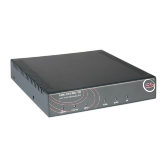
UHP Software 3.0 User Manual 3. State analysis There are several sources giving information about UHP status and problems. 3.1 Front panel indication UHP has six LED (Light Emitting Diode) indicators on the front panel. These indicators show status information and information flow through interfaces. -
Page 11: Events
UHP Software 3.0 User Manual Hardware errors inform about hardware problems with the router. Probably repair is needed. RAM fail Errors with router memory. LAN fail Errors with Ethernet interface. FPGA fail Errors in the programmable logic of router. Demodulator fail Errors with SCPC Rx interface. -
Page 12: Uhp Access For Configuration
With the fist connection of UHP-1000 Router to PC the system will request the device driver. UHP.INF driver is available on CD with documentation or can be downloaded from our web site. In response to the request for driver you should refuse from search in Internet and select setting from the specified place where UHP.INF is saved. -
Page 13: Command Interface
UHP Software 3.0 User Manual 5. Command interface UHP has command interface suitable for initial routing setup, monitoring and diagnostics. Command interface works equally when connecting via USB or Telnet or via local serial console (available in OEM versions of UHP). Telnet has precedence over USB and serial console. - Page 14 UHP Software 3.0 User Manual clear interface ethernet|demod|mod|tdma - Reinitialize interface clear arp-table - Purge contents of ARP table time set 0-24 0-60 1-31 1-12 0-99 - Set date/time HH MM DD MM YY unit key 0-15 [0-65535] [0-65535] [0-65535] - Set features key watchdog reset|interrupt - Watchdog timer overflow action...
-
Page 15: Http Interface
UHP Software 3.0 User Manual 6. HTTP interface 6.1 Introduction UHP has plenty of control and statistics parameters which will be described further. Some parameters can have many discrete values which will also be explained. To classify different parameters special style conventions were implemented: Style conventions WWW field Input field of WWW interface form changeable by user. -
Page 16: Statistics Frame
UHP Software 3.0 User Manual Multicast - IGMP protocol for videoconferencing Acceleration - TCP acceleration COTM/AMIP - Interface to mobile antennas Other - Other IP related settings - Quality of service settings Policies - Filtration, prioritization rules for IP packets Shapers - Rate limiting, guaranteed speeds Realtime BW allocation... -
Page 17: Main Screen Overview
UHP Software 3.0 User Manual 6.4 Main screen overview Overview screen shows thorough real time statistics of software modules. It is automatically refreshed every 30 seconds. In case of loosing a link to UHP browser can display error instead of information here. In this case user should refresh the page with browser "Refresh"... - Page 18 UHP Software 3.0 User Manual Active Number of active station s which are requesting bandwidth. Hub C/N low/high Number of stations having 1 dB lower/higher C/N on hub than set hub reference. Rem C/N low/high Number of stations having 1 dB lower/higher C/N on station than set remote reference.
- Page 19 UHP Software 3.0 User Manual NMS section This section appears only if access is activated. Current NMS IP address is shown. Document version 1.0, May 2013...
-
Page 20: Site Setup
UHP Software 3.0 User Manual 7. Site setup Site setup Site setup screen allows to configure UHP parameters related to installation site. First unit name is configured. This name appears in top frame and in Telnet command prompt. Location Site georgaphical location is specified. Location is used in TDMA timing calculations for stations and neseserity of location setup depends on timing mode selected. - Page 21 UHP Software 3.0 User Manual 10MHz Turns on 10 MHz signal on burst demodulator connector or modulator connector. SpInv Spectrum inversion Setup on RX or TX. Wrong setting will terminate the service. Frequency adjust Signed adjustment figures for two demodulators and modulator. Carrier search bw Range around set frequency (+/-) where carrier search is done by demodulators.
-
Page 22: Profiles
UHP Software 3.0 User Manual 8. Profiles 8.1 Profiles basics Profile is a set of settings needed to set up station or network service. UHP configuration includes 8 profiles. All of them are independent of one another. Each profile can be configured in any profile mode with appropriate set of settings. -
Page 23: Basic Profile Configuration
UHP Software 3.0 User Manual COTM stop Waiting if mobile antenna has disabled transmission or did not supply location. Start hub TX Turning on transmission on hub. Waiting for RX Waiting for demodulator to lock in modes requiring reception. Identify Determining station number and inroute from hub control information set in hub stations table Get net config... -
Page 24: Tdm/Scpc Rx
UHP Software 3.0 User Manual First and always existing tab is "Basic". This is a main profile parameters tab. Mode Profile mode. Valid Whether profile is valid (fully configured and usable). Autostart Whether profile can be automatically run by UHP (several profiles can be marked autostart). Timeout Timeout value counted down during profile state... -
Page 25: Tdm/Scpc Tx
UHP Software 3.0 User Manual This tab controls TDM/SCPC demodulator RF settings. Demodulator enable Enable demodulator operation. This field is omitted in mode where demodulator usage is not obligatory. Frequency Receive center frequency. SymRate Receive symbol rate. See limitations for S1/S2 standards in specification. Standard DVB-S1 / DVB-S2 mode switching. - Page 26 UHP Software 3.0 User Manual TLC - transmission level control allows to adjust local transmission level based on information about reception quality on remote side. Goal of TLC algoritm is to provide desired "reference level" (C/N on remote side. Reference must be selected to allow error free reception.
-
Page 27: Acm
UHP Software 3.0 User Manual to ensure optimal level of reception on the receiving site. TLC can be activated for both or just one direction of duplex SCPC link. In contrast to TLC in the TDM/TDMA networks and HUBLESS TDMA, SCPC TLC parameters are transmitted between stations over UDP, which allows you to send them both via satellite and by terrestrial networks. -
Page 28: Tdma Rf
UHP Software 3.0 User Manual 2 - QPSK 3/4 3 - QPSK 5/6 4 - QPSK 8/9 Medium range: 1 - QPSK 2/3 2 - QPSK 5/6 3 - 8PSK 2/3 4 - 8PSK 8/9 High range: 1 - QPSK 2/3 2 - QPSK 8/9 3 - 8PSK 5/6 4 - 16APSK 3/4... -
Page 29: Tdma Timing
UHP Software 3.0 User Manual TDMA protocol Inroute number Number of inroute channel. Should be unique for each hub inroute. Frame length Length of TDMA frame time slot Must be multiple of four. At high symbol rates in MF TDMA mode automatically rounded down to nearest 8 or 16. -
Page 30: Crosspol Rf
UHP Software 3.0 User Manual on several factors (symbol rate, TDMA burst duration) and is presented in TDMA statistics. Usually, TDMA burst duration lies in the range from 500 to 10,000 us, and thus calculated DTTS value accuracy lies in the range from 63 to 1,250 us. This accuracy is sufficient for Hub to capture station without causing interference to other stations. -
Page 31: Return Channel
UHP Software 3.0 User Manual idle - stations in the network but not requesting bandwidth. active - stations in the network and making requests for bandwidth. Each group is assigned a probability with which Hub will allocate a bandwidth to stations belonging to this group. The term "allocate a bandwidth"... - Page 32 UHP Software 3.0 User Manual Document version 1.0, May 2013...
-
Page 33: Routing And Bridging
9.1 SVLAN overview UHP-1000 routers make use of a special protocol to transmit information via the satellite. Requirements to such protocol are minimal overhead and a possibility to split and group data streams. With the UHP-1000 routers, this protocol is named SVLAN. -
Page 34: Ip Address
UHP Software 3.0 User Manual Routing Table Strings description: Bridge - VLAN 5 is bridged to satellite SVLAN 67 IP addr - IP address 10.0.0.11/24, untagged Tagged IP - IP address 10.0.0.11/24 in VLAN 7 TX map 1 - Network 20.0.0.0/24 routed to satellite SVLAN 11, low priority, to station 2 High prio - Network 40.0.0.0/20 routed to satellite SVLAN 33, high priority, to station 888 Pol CIR... -
Page 35: Static Route
UHP Software 3.0 User Manual PolDrops Number of packets dropped by all policies. Warning: Maximal value of packets counters on this screen is 65535. Then they continue counting from 0. 9.4 IP address IP address VLAN VLAN number or 0 for untagged. IP address IP address. -
Page 36: Vlan Bridge
UHP Software 3.0 User Manual TX map VLAN VLAN number or 0 for untagged. IP network IP network. Net mask Network mask in dotted (255.255.255.0) or classless (/24) notation. SVLAN SVLAN number. Station Station number. Map traffic will be counted as TX traffic towards this station. Priority/policy Fixed priority or policy mode. -
Page 37: Svlan Receive
UHP Software 3.0 User Manual Shaper channel selection. Title Optional title. 9.8 SVLAN Receive SVLAN Receive VLAN VLAN number or 0 for untagged. SVLAN SVLAN number to receive. Title Optional title. Document version 1.0, May 2013... -
Page 38: Ip Protocols
UHP Software 3.0 User Manual 10. IP Protocols 10.1 SNMP UHP router supports SNMP protocol versions V1 and Community-based V2. The following SNMP classes are supported: .iso.org.dod.internet.management.mib2. system. interfaces. private.enterprises.UHP.uhpV30. Information about variables can be obtained from the MIB file supplied with the router. SNMP Read community Password for reading SNMP variables. -
Page 39: Sntp
UHP Software 3.0 User Manual IP start First IP address of DHCP pool. IP end Last IP address of DHCP pool. Mask Network IP mask to report. IP gateway Gateway IP to report (usually one of IP addresses of UHP). DNS server DNS server to report (supplied by ISP). -
Page 40: Tftp
UHP Software 3.0 User Manual Transmission of such packets via a satellite is extremely inefficient with respect to bandwidth usage, hence use is made of compression of protocols headers based on the fact that only few fields change from placket to packet, and furthermore this change can often be predicted. -
Page 41: Multicast
UHP routers support IGMP version 1-3, as well as static routing of multicast traffic. Static routing of multicast traffic is implemented in UHP-1000 routers as follows: To collect Multicast traffic from LAN to specified address you have to assign a map for this traffic on the modulator. The router will itself understand that the address (network) belongs to the Multicast range and will tune LAN to receive it. -
Page 42: Cotm/Amip
UHP Software 3.0 User Manual Acceleration Enable Enable acceleration. Allow from SVLAN Allow SVLANS from ... to be accelerated. Used to make un-accelerated subnetwork. Allow to SVLAN Allow SVLANS to ... to be accelerated. MTU to set in accelerated packets. TCP window TCP window to set in accelerated packets. -
Page 43: Other Settings
IP screening To avoid this situation, UHP-1000 router is provided with a special mechanism - IP screening. This mechanism works as follows: each packet received from satellite gets a tag. If during routing this packet tries to go back to the satellite it will be dropped. -
Page 44: Policies
UHP Software 3.0 User Manual 11. QOS Quality of service in UHP has several mechanisms providing prioritizing and traffic regulation. QOS scheme 11.1 Policies Policies allow to classify IP packets and according to classification to perform certain actions on this packets. UHP contains list of policies. - Page 45 UHP Software 3.0 User Manual Policy On the picture green arrows mean successful checks, red arrows - unsuccessful checks, black arrows - unconditional jumps. In this policy first destination IP address AND destination UDP port is checked. If they match RTP compression is performed.
-
Page 46: Shapers
UHP Software 3.0 User Manual Policy rule Checks 802.1q priority Match priority field of VLAN tag. VLAN Match VLAN value. Match TOS byte value. DSCP Match DSCP bits value. Protocol Match IP protocol. ICMP type Match ICMP protocol message type. SRC IP Match source IP address / network. - Page 47 UHP Software 3.0 User Manual 11.2 Shapers Traffic shaper (TS) is intended for adjustment of the bandwidth occupied by data streams transmitted via a satellite. TS is based om set of channels - controlled "pipes" for traffic between router and modulator. Passing traffic to the channel - Traffic is routed to the channel by setting channel number in record of routing table.
- Page 48 UHP Software 3.0 User Manual Shapers Template shaper Activates template mode for station shapers. (NMS behaves differently, see manual!) Guaranteed speed. Initial value of CB. Title Optional title of shaper. Upper channel Enabling upper channel for shaper. If not enabled then modulator is upper channel. Channel Upper channel number.
-
Page 49: Real-Time
UHP Software 3.0 User Manual Spd.K Current input rate of channel. Percent of CIR. Del. Delay in seconds generates by channel. LowSp Input rate of low priority queue. MedSp Input rate of medium priority queue. HigSp Input rate of high priority queue. BW.K Current channel bandwidth. -
Page 50: Service Monitoring
UHP Software 3.0 User Manual requested (16K). 2. Second call starts. Traffic exceeded value of 20K (codec + threshold). Dual codec-rate bandwidth is requested (32K). 3. One of calls drops. Station still does not decrease its bandwidth request, since it does not know whether the call is completed or whether there is just a pause. - Page 51 UHP Software 3.0 User Manual IP address IP address to PING. Delay Whether to check delay. Connectivity check should be enabled. lower than Delay must be lower than this value. Network service is service towards hub and network beyond hub. Again, not obligatory. Link Whether to check connectivity.
-
Page 52: Network Overview
UHP Software 3.0 User Manual 12. Network 12.1 Network Overview This statistics screen shows overall network parameters and statistics. Not all sections are shown in various modes. Network overview is also available by # show network command. --------------------------- Unit state --------------------------- Mode: none State: Init ------------------------- Identification -------------------------... - Page 53 UHP Software 3.0 User Manual NoBurst ZeroSt Number of times frame plan was not filled entirely - unassigned slots left. FpLost Frame plans lost due to forward channel problems. ---------------------------- Station ----------------------------- Number Station number decoded from hub information. CurBw Currently assigned bandwidth.
- Page 54 UHP Software 3.0 User Manual Stations Number Station number. Enable station. Serial number of station UHP. Shaper Traffic shaper channel settings to use in guaranteed bandwidth calculations. Req-pr. Bandwidth bandwidth request profile to use. Group actions on stations. From st From station.
-
Page 55: Mf-Tdma
UHP Software 3.0 User Manual Remote station number. Bytes_rcvd Number of bytes received from station. CRC_errs Number of CRC errors. Number of time slots currently requested by station. Number of time slots currently assigned to station. C/N value on hub. Offset Frequency offset in Hertz. -
Page 56: Statistics Of Acm
UHP Software 3.0 User Manual Changes Number of times controller state changed. 12.4 Statistics of ACM This statistics shows ACM sub-channels operation. MODCOD CN_min CN_cor Stations Frames_TX Bytes_TX QPSK-2/3 QPSK-5/6 QPSK-8/9 8PSK-5/6 Channel number. MODCOD MODCODs of sub-channels. First is set in profile TDM/SCPC TX , others in CN_min... - Page 57 Number of password errors occured. 12.5.3 Redundancy To organize a HUB with a hot redundancy function for a TDM/TDMA hub two UHP-1000 routers with the TDM/TDMA hub function. Every router has to be connected to transmit and receive paths of the station.
- Page 58 UHP Software 3.0 User Manual Redundancy is disabled. Fault Last try to start network was unsuccessful. Backup Backup mode. Peer is running the network. Trying Trying to run the network. Active This unit is running the network. When started, the router is in BACKUP mode. In this mode the router starts a ten seconds timer. During this time a message reporting the status of the second router is awaited.
- Page 59 UHP Software 3.0 User Manual Redundancy states IP routing has specific issues in redundancy mode. First of all an IP address must be configured on UHP which becomes "Monitoring" IP address. Other IP addresses which are used for user data forwarding are called "Data" addresses. When UHP is in TRYING/ACTIVE mode all IP routing works as usual.
- Page 60 UHP Software 3.0 User Manual Remote IP Peer IP for redundancy. Should be set as local IP on another side. Local IP Local IP address to leave operating in redundant mode. Fault timeout Timeout which allows units to prepare themselves for operation and establish link with one another.
- Page 61 UHP Software 3.0 User Manual 13. System 13.1 Overview Overall UHP status is shown. Keys and system errors are shown. UHP ACM DVB-S1 SW3 Ver: 2.9.6 (Jan 23 2013 D1/M1) SN: 00001699 Uptime: +05:48:22 CurrentTime: +05:48:22 TimeShift: 0 RateAvgTime: 5 BuffersFree: 1286 NoBuffer: 0 ScDesc: 4063...
-
Page 62: Ethernet Statistics
UHP Software 3.0 User Manual Interfaces Overall interfaces control. LAN interface. Mode Link and duplex mode selection. Demodulator interface. Pointing voltage Enables DC voltage on USB connector proportional to demodulator C/N. Slope dB/V Regulates how many dB correspond to one volt of output. Modulator queues length limits in packets. -
Page 63: Demodulator Statistics
UHP Software 3.0 User Manual Number of transitions to DOWN. U->D transitions Time when the last cleaning of counters occurred. Counters reset These counters are reset together with statistics counters on the relevant commands. Then information on the specific interfaces comes up. MAC: 46:13:00:00:16:99 Set: AUTO State: 100/Full|TX queue | 0... -
Page 64: Modulator Statistics
UHP Software 3.0 User Manual LDPC LDPC FEC rate. Can vary in ACM mode. SRoff Symbol frequency error in symbols per second. Signal to noise ratio. RX-offset Receive frequency offset between set and actual values. Rate/bps Input information rate in Bps. Packets Packets received. -
Page 65: User Access
UHP Software 3.0 User Manual Time-related Time zone Time shift with GMT in +/- hours. Speed count interval Interval for averaging traffic on interfaces. Console timeout Timeout for Telnet or console inactivity auto-logout. 13.7 User access Initially UHP has no passwords defined. Passwords for user (read only + reboot) and administrator (full access) are set here. - Page 66 UHP Software 3.0 User Manual Boot procedure Flash/Boot Bank Bank number. Image Image type loaded. Version Image version. Length Image length in bytes. Date Date of image compilation. Main boot Main boot flash bank and configuration bank. Auto - scan through banks sequentially from bank 1 and boot from any bank containing valid image.
- Page 67 UHP Software 3.0 User Manual 13.9 Save/Load Configuration saving and loading screen. UHP has 2 banks of configuration. Each bank holds entire configuration with 8 profiles, routing, stations. Bank o is loaded by default. Save/Load SW Version Version of software which saved config. Sequence Increased by 1 after each saving.
-
Page 68: Support Information
UHP Software 3.0 User Manual 14. Maintenance 14.1 Support information This screen has set of statistics for reporting to technical support center within support requests. This information will be important for knowing current configuration of UHP and preparing accurate answer. Set of statistics is not complete so possibly other statistics may be requested by support center to clarify situation. -
Page 69: Network Command
UHP Software 3.0 User Manual also shown below when demodulator is unlocked. Please allow demodulator to pass all search cycle before changing azimuth and/or elevation angle. When demodulator locks on the carrier textual and graphical information about level C/N will replace the information about search phase. Proceed with fine-tuning of antenna azimuth and elevation until a maximum of C/N level is achieved. -
Page 70: Traffic Generator
UHP Software 3.0 User Manual Network Command Serial number of remote UHP or 11111111 (eight ones) for broadcast command to all stations. Command Command itself. Commands which need pausing should not be used. They can block remote end console. 14.4 Traffic generator Traffic generator generates PING packets. - Page 71 UHP Software 3.0 User Manual Document version 1.0, May 2013...
Need help?
Do you have a question about the UHP-1000 and is the answer not in the manual?
Questions and answers