Table of Contents
Advertisement
O
M
PERATOR'S
ANUAL
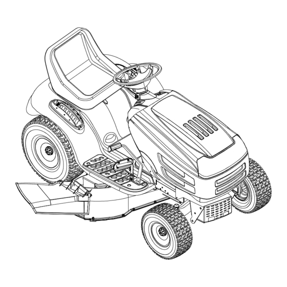
Automatic Transmission Lawn Tractor
Models 1170
1180
IMPORTANT: READ SAFETY RULES AND INSTRUCTIONS CAREFULLY
Warning:
This unit is equipped with an internal combustion engine and should not be used on or near any unimproved forest-
covered, brush-covered or grass-covered land unless the engine's exhaust system is equipped with a spark arrester meeting
applicable local or state laws (if any). If a spark arrester is used, it should be maintained in effective working order by the operator.
In the State of California the above is required by law (Section 4442 of the California Public Resources Code). Other states may have
similar laws. Federal laws apply on federal lands. A spark arrester for the muffler is available through your Cub Cadet dealer or con-
tact the service department, P.O. Box 368023 Cleveland, Ohio 44136-9722.
CUB CADET CORP. P.O. BOX 368023 CLEVELAND, OHIO 44136-9722
PRINTED IN U.S.A.
FORM NO. 770-10249B
(9/99)
Advertisement
Table of Contents

Related Manuals for Cadet 1170


Summary of Contents for Cadet 1170
- Page 1 In the State of California the above is required by law (Section 4442 of the California Public Resources Code). Other states may have similar laws. Federal laws apply on federal lands. A spark arrester for the muffler is available through your Cub Cadet dealer or con- tact the service department, P.O.
-
Page 2: Table Of Contents
Operator’s Manual. The information on the model plate is very important if you need help from your Cub Cadet dealer. • Every tractor has a model plate. You can locate it by lifting the seat and looking at the seat bracket. -
Page 3: Important Safe Operation Practices
SECTION 4: IMPORTANT SAFE OPERATION PRACTICES WARNING: THIS SYMBOL POINTS OUT IMPORTANT SAFETY INSTRUCTIONS WHICH, IF NOT FOLLOWED, COULD ENDANGER THE PERSONAL SAFETY AND/OR PROPERTY OF YOURSELF AND OTHERS. READ AND FOLLOW ALL INSTRUCTIONS IN THIS MANUAL BEFORE ATTEMPTING TO OPERATE YOUR LAWN MOWER. FAILURE TO COMPLY WITH THESE INSTRUCTIONS MAY RESULT IN PERSONAL INJURY. -
Page 4: Slope Operation
• Disengage all attachment clutches, thoroughly 3. CHILDREN depress the brake pedal, and shift into neutral Tragic accidents can occur if the operator is not alert to the before attempting to start engine. presence of children. Children are often attracted to the •... -
Page 5: Safety Lables Found On Your Unit
• Keep all nuts, bolts and screws tight to be sure the • Do not change the engine governor settings or equipment is in safe working condition. overspeed the engine. Excessive engine speeds are dangerous. • Never tamper with safety devices. Check their proper operation regularly. -
Page 6: Slope Gauge
Slope Gauge... -
Page 7: Attachments & Accessories
SECTION 5: ATTACHMENTS & ACCESSORIES MODEL NUMBER DESCRIPTION OEM-190-601 FastAttach Twin Bagger Grass Collector (For 42-inch Decks Only) ™ OEM-190-602 FastAttach Twin Bagger Grass Collector (For 46-inch Decks Only) ™ OEM-190-112 Mulch Kit (For 42-inch Decks Only) OEM-190-118 Mulch Kit (For 46-inch Decks Only) OEM-190-603 FastAttach Grille Guard... -
Page 8: Controls
SECTION 7: CONTROLS NOTE: Steering Wheel not shown for clarity Figure 3 Ignition Switch Brake Pedal Throttle Control Lever Parking Brake Button Choke Control (if so equipped) Shift Lever Indicator Monitor/Hour Meter Seat Adjustment Lever Lift Lever Cup Holder PTO (Power Take-off) Knob M Cruise Control Button G Drive Pedal NOTE:... -
Page 9: Ignition Switch
The throttle lever is located on the right side of the Hour tractor’s dash panel. This lever controls the speed of Meter the engine, and on Model 1170, the choke control also. When set in a given position, the throttle will 1/10 maintain a uniform engine speed. See Figure 5. -
Page 10: Lift Lever
LIFT LEVER BRAKE PEDAL BRAKE The brake pedal is located on the right front side of The lift lever is used to change the operating position the tractor above the drive pedal along the running (height) of the cutting deck. To operate, move the board. -
Page 11: Operation
Safety Interlock Switches in any interlock system should ever malfunction, do not way WILL void your warranty. operate the tractor. Contact a Cub Cadet dealer in your area. The safety interlock system prevents the engine from cranking or starting unless the brake... - Page 12 SETTING THE CUTTING HEIGHT STOPPING THE ENGINE Select the height position of the cutting deck by • Place the PTO knob in the disengaged (OFF) placing the deck lift lever in any of the six different position cutting height notches on the right side of the fender. •...
-
Page 13: Stopping The Engine
• While continuing to hold the cruise button in, To turn the tractor’s headlights off: lift your foot from the drive pedal (you should • Turn the key either into the On position (to feel the cruise latch engage). leave the engine running) or the Off position •... -
Page 14: Adjustments
MOWING • Under heavier conditions it may be necessary This tractor is equipped with one of Cub Cadet’s to go back over the cut area a second time to high quality cutting decks. The following information get a clean cut. -
Page 15: Seat Adjustment
Side to Side If the cutting deck appears to be mowing unevenly, a side to side adjustment can be performed. Adjust if necessary as follows: WARNING: Turn the tractor’s engine off, remove the key from the ignition switch and apply the tractor’s parking brake before making any adjustments to the cutting deck. -
Page 16: Carburetor Adjustment
Adjust the drag links so that equal lengths are CARBURETOR ADJUSTMENT threaded into the ball joint on the left side and the WARNING: adjustments ball joint on the right side: made to the engine while the engine is • Loosen the jam nut found on the drag link at running (e.g. -
Page 17: Maintenance
SECTION 10: MAINTENANCE WARNING: IMPORTANT: Disconnect the spark plug Refill the engine with the proper wire(s) and ground against the engine capacity and weight of motor oil as instructed in the before performing any adjustments, repairs separate engine manual. or maintenance. Service air cleaner every 25 hours under normal conditions. -
Page 18: Changing The Deck Belt(S)
• Grasp the PTO idler pulley bracket and pivot it • Repeat the above steps on the left side of the toward the discharge chute to relieve tension tractor. on the belt. Remove the deck belt from around • Move the lift lever into the top notch on the the electric PTO clutch and the PTO idler right fender to raise the deck lift arms out of pulley. - Page 19 • Route the new belt as shown in Figure 14, around the deck pulleys, idler pulley and electric PTO clutch. • Remount the belt guards removed earlier. Electric PTO Clutch PTO Idler Pulley Deck belt (Bottom) (mounted on tractor) PTO belt (Top) Deck Idler Pulley Right Hand Double Pulley...
- Page 20 Proper removal of the lower drive belt requires the removal of several tractor components. Read through the following procedure prior to attempting it to determine if you feel you could successfully complete it. If you don’t, see your Cub Cadet dealer to have the belt changed. IMPORTANT: Note the routing of the lower drive belt around both the pulleys and the belt keepers BEFORE performing the following steps.
- Page 21 • Slide the belt off of the variable-speed pulley The drive pedal is properly adjusted when the hole as you lift the pulley up and out through the found in the double-idler bracket has approximately battery tray opening. 1-3/8" of travel with ten pounds of pressure applied to the drive pedal.
- Page 22 CUTTING BLADES WARNING: Cutting blades are sharp. Always protect hands by wearing heavy leather work gloves to grasp blades. Worn Blade Edge The blades may be removed for sharpening or Wind Wing Blade Separation replacement as follows. • Remove the deck from beneath the tractor, (refer to DECK REMOVAL earlier in this section for detailed instructions) then gently flip the deck over to expose its underside.
-
Page 23: Lubrication
Charging FUSE If the unit has not been put into use for an extended A fuse is installed in your tractor’s wiring harness to period of time, charge the battery with an protect the tractor’s electrical system from damage automotive-type 12-volt charger for a minimum of caused by excessive amperage. -
Page 24: Troubleshooting Guide
Spark plug lead disconnected. Connect lead. Using a spark tester, check for spark. If spark plug(s). no spark is present, have engine’s magneto serviced by your Cub Cadet dealer. Dirty aircleaner. If the air cleaner is dirty, the engine may not start. Refer to the engine manual packed with your unit. - Page 25 Models 1170 & 1180 Electrical System 18/19 REF. PART DESCRIPTION 625-0051 Bulb/Socket Headlight Assembly 629-0939 Wiring Harness w/o Ref. 14 629-0126 Harness Adapter, #18 x 5 710-0599 Self Tapping Screw, 1/4-20 x .5 712-3006 Hex Nut, 1/4-20 725-1426 Solenoid, 12-volt, 100 Amp...
- Page 26 Models 1170 & 1180...
-
Page 27: Parts List
Machine Screw, #10-24 751-0603 Fuel Cap Model 1170 has no choke knob/cable. The choke is activated with the throttle cable. Refer to Engine Accessories on pg. 39. NOTE: For painted parts, please refer to the list of color codes below. Please add... - Page 28 Models 1170 & 1180...
- Page 29 Lift Assembly REF. PART REF. PART DESCRIPTION DESCRIPTION 747-1130 Deck Stabilizer Rod 710-0805 Carriage Bolt, 5/16-18 x 1.5 683-0197 Lift Shaft Assembly 710-0604A Self-tapping Screw, 5/16-18 x .625 711-0332 Clevis Pin, .5 x .78 710-0895 Self-tapping Screw, 1/4-15 x .75 712-0206 Hex Nut, 1/2-13 731-1990...
- Page 30 Models 1170 & 1180...
-
Page 31: Steering Assembly
638-0021 LH Axle Assembly, .625 / .750 Diameter NOTE: Model 1170 has axles with a .625 diameter. Model 1180 has axles with a .625 / .750 diameter. NOTE: For painted parts, please refer to the list of color codes below. Please add... - Page 32 Models 1170 & 1180...
-
Page 33: Drive System
Drive System REF. PART REF. PART DESCRIPTION DESCRIPTION 783-1015 Shift Lever Support 783-0667A Transmission Torque Bracket 17840 Transaxle Mounting Bracket 783-0669 Idler Bracket 618-0307C Single-speed Transmission Assembly 783-0714 Adjustable Shift Bracket 631-0009 Shifter Knob 647-0031 Brake Control Assembly 647-0045 Shift Lever 647-0032 Speed Control Assembly 656-0048... - Page 34 Models 1170 & 1180 Units with 618-0307C Transmission ONLY...
- Page 35 Single-speed Transmission REF. PART DESCRIPTION 618-0318 Clutch Collar† 710-0788 Self-tapping Screw, 1/4-20 x 1.0 711-1274 Drive Shaft 711-1280 Counter Shaft 713-0474 22-link Chain, #420 713-0478 14-tooth Sprocket 717-1422 Sprocket Bevel Gear, 42/10 717-1565 29-tooth Spur Gear 717-1569 20-tooth Spur Gear 718-0652 Counter Shaft Coupling 719-0394...
- Page 36 Models 1170 & 1180...
- Page 37 Power Take-off System REF. PART REF. PART DESCRIPTION DESCRIPTION 712-0431 Flange Lock Nut, 3/8-16 712-3010 Hex Nut, 5/16-18 732-0735 Compression Spring, 1.318 x 2.37 710-3180 Hex Cap Screw, 5/16-18 x 1.75 (Grade 5) 783-0733 Spacer Cup, 1.5 OD 732-0978 Extension Spring, 1.2 OD x 3.638 732-0956 Compression Spring, .66 OD x 1.5 710-1650...
-
Page 38: Inch Deck
Models 1170 & 1180 46-inch Deck 42-inch Deck... -
Page 39: Cutting Decks
Cutting Decks REF. PART REF. PART DESCRIPTION DESCRIPTION 17982 Reinforcement Spindle Plate 742-0611 Three-in-one Blade, Star Center, 16.28 618-0430 Spindle Assembly w/ Fitting, 5 Dia. 742-0612 Three-in-one Blade, Star Center, 14.88 618-0431 Double Pulley Spindle Assembly w/ Fitting 747-1116 Deck Release Pin 683-0254 Deck Adjustment Bracket w/ Weld Nut 754-0349... - Page 40 Models 1170 & 1180 (for choke) Briggs & Stratton Intek Twin (for throttle) (deflector must face forward) Briggs & Stratton Intek Single (deflector must face forward)
- Page 41 Engine Accessories REF. PART DESCRIPTION 710-0148 Self-tapping Screw, #8-32 x .375 710-0599 Self-tapping Screw, 1/4-20 x .5 710-0604A Self-tapping Screw, 5/16-18 x .625 710-1237 Screw, #10-32 x .625 710-1314 Socket Cap Screw, 5/16-18 x .625 710-1315 Self-tapping Screw, 3/8-16 x 1.25 712-3017 Hex Nut, 3/8-16 721-0460...
-
Page 44: Cub Cadet Corp
MANUFACTURER’S LIMITED WARRANTY FOR: c. Log splitter pumps, valves and cylinders have a sepa- The limited warranty set forth below is given by Cub Cadet rate one year warranty. Corp. with respect to new merchandise purchased and d. Cub Cadet Corp. does not extend any warranty for used in the United States, its possessions and territories.
Need help?
Do you have a question about the 1170 and is the answer not in the manual?
Questions and answers