Table of Contents
Advertisement
IMPORTANT: Read safety rules and instructions carefully
WARNING:
This unit is equipped with an internal combustion engine and should not be used on or near any unimproved forest-
covered, brush-covered or grass-covered land unless the engine's exhaust system is equipped with a spark arrester meeting applicable
local or state laws (if any). If a spark arrester is used, it should be maintained in effective working order by the operator. In the State of
California the above is required by law (Section 4442 of the California Public Resources Code). Other states may have similar laws. Federal
laws apply on federal lands. A spark arrester for the muffler is available through your nearest engine authorized service dealer or contact the
service department, P.O. BOX 361131 CLEVELAND, OHIO 44136-0019
PRINTED IN U.S.A.
Operator's Manual
Cub Cadet LLC, P.O. BOX 361131 CLEVELAND, OHIO 44136-0019
Riding Mower
Internal Bagging System
27.5" Cutting Deck
Model 1027
FORM NO. 770-10094D.fm
(11/2001)
Advertisement
Table of Contents

Related Manuals for Cadet 1027


Summary of Contents for Cadet 1027
- Page 1 A spark arrester for the muffler is available through your nearest engine authorized service dealer or contact the service department, P.O. BOX 361131 CLEVELAND, OHIO 44136-0019 Cub Cadet LLC, P.O. BOX 361131 CLEVELAND, OHIO 44136-0019 PRINTED IN U.S.A.
-
Page 2: Table Of Contents
(Model Number) (Serial Number) Copy the model number here: Copy the serial number here: CUB CADET LLC P. O. BOX 361131 www.cubcadet.com CLEVELAND, OH 44136 DEALER LOCATOR PHONE NUMBER: 877-282-8684 ENGINE INFORMATION The engine manufacturer is responsible for all engine-related issues with regards to performance, power- rating, specifications, warranty and service. -
Page 3: Important Safe Operation Practices
SECTION 1: IMPORTANT SAFE OPERATION PRACTICES WARNING: This symbol points out important safety instructions which, if not followed, could endanger the personal safety and/or property of yourself and others. Read and follow all instructions in this manual before attempting to operate your riding mower. Failure to comply with these instructions may result in personal injury. - Page 4 on the mower deck or contact the engine exhaust Never assume that children will remain where you presenting a potential fire hazard. last saw them. • Keep children out of the mowing area and in Slope Operation watchful care of an adult other than the operator. •...
- Page 5 • Never tamper with safety devices. Check their • Do not change the engine governor settings or proper operation regularly. Use all guards as overspeed the engine. Excessive engine speeds instructed in this manual. are dangerous. • After striking a foreign object, stop the engine, •...
-
Page 6: Slope Gauge
SECTION 2: SLOPE GUAGE USE THIS PAGE AS A GUIDE TO DETERMINE SLOPES WHERE YOU MAY NOT OPERATE RIDING MOWER SAFELY:... -
Page 7: Assembling Your Riding Mower
SECTION 3: UNPACKING & ASSEMBLING YOUR RIDING MOWER • Remove all screws and staples from the crate. • Remove both wing nuts securing the battery and • Holding sides of the crate firmly, lift top of the crate cover to the battery hold-down rods. See Figure 3 . up and set it aside. - Page 8 • To attach the mulching plug now to the unit, follow WARNING: Do not operate the mower if any instructions on previous page to attach side- one or more of the grass catcher, discharge discharge chute to the deck. chute or mulching plug is not firmly installed on •...
-
Page 9: Know Your Riding Mower
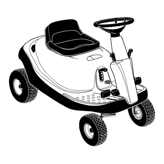
SECTION 4: KNOW YOUR RIDING MOWER Compare the illustrations in Figure 8 with your riding mower to familiarize yourself with the location of various controls and adjustments. WARNING: The operation of any riding mower can result in foreign objects being thrown into the operator’s eyes, causing severe eye damage. -
Page 10: Stopping Mower
Blade Engagement Pedal • Before you move the shift lever to any of the positions, depress the brake pedal and stop the Use to engage or disengage the blade. unit. Keep your foot on the brake pedal. Blade Lock Use to lock blade at the engaged position. Cutting Height Adjustment Lever Use to raise and lower the cutting deck which determines the cutting height. -
Page 11: Operating Your Riding Mower
SECTION 5: OPERATING YOUR RIDING MOWER Using Throttle/Choke Control • Turn the ignition key to the START position. As soon as the engine starts, let the key return to the The throttle/choke control is used to increase or ON position. decrease the speed of the engine.The FAST and the •... -
Page 12: Using The Mower
grasscatcher bag by the handle and take it to the • When mowing an area for the first time, watch out proper disposal site. See Figure 11 . for objects lying on the grass. If you strike a foreign • Hold the bag away from your body. -
Page 13: Making Adjustments
SECTION 6: MAKING ADJUSTMENTS “Go” Pedal WARNING: Do not at any time make any Adjustment to the "Go" Pedal is made at the cable end. adjustment to the mower without first stopping See Figure 12 . engine and disconnecting spark plug wire. •... -
Page 14: Seat Position
Seat Position • If the belt is slipping when you depress the blade engagement pedal about 3/4”, loosen the two hex The seat position on the riding mower can be adjusted nuts on the cable. See Figure 13. to maximize the operator’s convenience. •... - Page 15 • Inspect rear of deck. If the deck is contacting the • Measure the distance from the tips of the blade to cable bracket on the front of the transmission, you the ground. will have to adjust the rear deck height. •...
-
Page 16: Servicing Your Riding Mower
SECTION 7: SERVICING YOUR RIDING MOWER Fuse Replacement Imaginary The fuse is located next to the spark plug under the rear Line Belt Belt frame. Fuses seldom fail without a reason. If the fuse Keeper “A” Keeper blows, the source problem must be corrected or the Deck Belt new fuse will blow again. -
Page 17: Maintaining Your Riding Mower
• Using a 9/16” socket, remove bolt, spacer and the • Drop the pulley down and remove the belt. flat washer from the variable speed pulley. See • Replace new belt and reassemble. Figure 17 . • Make sure that the belt is routed inside of belt keeper, and the belt keeper is reassembled in the Variable Speed Pulley same location from where it was removed. - Page 18 Lubrication • The blade can be tested for balance by balancing it on a round shaft screwdriver. Remove metal from See Figure 20 for an illustration of the lube points the heavy side until it balances evenly. described below. Reassembly •...
-
Page 19: Off-Season Storage
• Lubricate teeth of the external steering gears with • Using a brush or cloth, remove grass, chaff or automotive multi-purpose grease every 25 hours of debris from the finger guard on the engine daily to operation or once a season. prevent overheating of the engine. -
Page 20: Troubleshooting
SECTION 10: TROUBLE-SHOOTING Trouble Possible Cause Remedial Action Excessive vibration 1. Bent or damaged blade 1. Stop engine immediately. Check all pulleys, blade adapters, keys and bolts for tightness and spindle damage. Tighten or replace any damaged parts. 2. Bent blade. 2. - Page 21 2. Replace defective part. 3. Engine loses crankcase vacuum 3. Engine breather defective. Replace. For repairs beyond those listed in the Trouble-Shooting chart above, please contact an authorized service dealer or call Cub Cadet Dealer Referral Line at 1- (877)-282-8684.
-
Page 22: Parts List
SECTION 11: PARTS LIST FOR MODEL 1027 NOTE: For painted parts, please refer to the list of color codes below. Please add the applicable color code, wherever needed, to the part number to order a replacement part. For instance, if a part, numbered 700-xxxx, is painted Cub Yellow, the part number to order would be 700-xxxx-0716. - Page 23 Model 1027 Ref. No. Part No. Description Ref. No. Part No. Description 17962 Switch Plate 731-0511 Trim Strip 650-0007 Steering Tube Assembly 735-0674 Floor Pad: LH 683-0033A Steering Support Bracket 735-0266A Floor Pad: RH 683-0178A Front Axle Assembly: RH 736-0105...
- Page 24 Model 1027 NOTE: For painted parts, please refer to the list of color codes below. Please add the applicable color code, wherever needed, to the part number to order a replacement part. For instance, if a part, numbered 700-xxxx, is painted Cub Yellow, the part number to order would be 700-xxxx-0716.
- Page 25 Model 1027 Ref. No. Part No. Description Ref. No. Part No. Description 683-0155A Brake Pedal Assembly 736-0187 Flat Washer 683-0161 Shift Cam Assembly 736-0262 Flat Washer 683-0275A Deck Pedal Assembly 736-0272 Flat Washer .510 X 1.00 X .060 683-0310A Variable Pedal Assembly...
- Page 26 Model 1027 13 23 Ref. No. Part No. Description Ref. No. Part No. Description 683-0152 Pivot Link Assembly 732-0829 Extension Spring 683-0194A Lift Arm Assembly 732-0837 Torsion Spring 710-0376 Hex Screw 5/16-18 X 1.00 Gr.5 736-0119 Lock Washer 5/16 710-3230 Hex Bolt 1/2-13 X 2.75 Gr.5 Spec.
- Page 27 Model 1027 Ref. No. Part No. Description 629-0865 Harness Assembly Adapter 710-1208 Hex TT Screw 5/16-18 x 3.50 710-0227 Hex Washer Head Self-Tap.Scew 710-0805 Hex Screw 5/16-18 x 1.5 Gr. 5 710-0642 Thd. Forming Scr. 1/4-20x .75 712-3010 Hex Nut 5/16-18...
- Page 28 Model 1027 IMPORTANT: For a proper working machine, use Factory Approved Parts. V-BELTS are specially designed to engage and disengage safely. substitute (non OEM) V-Belt can be dangerous disengaging completely. Ref. No. Part No. Description Ref. No. Part No. Description...
- Page 29 Model 1027 NOTE: For painted parts, please refer to the list of color codes below. Please add the applicable color code, wherever needed, to the part number to order a replacement part. For instance, if a part, numbered 700-xxxx, is painted Cub Yellow, the part number to order would be 700-xxxx-0716.
- Page 30 Model 1027 NOTE: For painted parts, please refer to the list of color codes below. Please add the applicable color code, wherever needed, to the part number to order a replacement part. For instance, if a part, numbered 700-xxxx, is painted Cub Yellow, the part number to order would be 700-xxxx-0716.
- Page 31 Model 1027 Ref. No. Part No. Description Ref. No. Part No. Description 683-0149B Frame Assembly 731-1682A Oil Drain Sleeve 683-0190A Frame Rail Support: RH 731-1945A Engine Duct 683-0191A Frame Rail Support: LH 732-3080A Compression Spring 683-0192 Muffler Pipe Extension 735-0273...
- Page 32 Model 1027 NOTE: For painted parts, please refer to the list of color codes below. Please add the applicable color code, wherever needed, to the part number to order a replacement part. For instance, if a part, numbered 700-xxxx, is painted Cub Yellow, the part number to order would be 700-xxxx-0716.
- Page 33 Model 1027 Ref. No. Part No. Description 618-0232 Differential Assembly: Single Speed 618-0248 Drive Shaft assembly: LH Brake 618-0072B Upper Housing Assembly 611-0114 Detent Shaft Assembly 661-0006 Brake Yoke Assembly: LH 710-1206 Hex Washer Hd. TT Screw 1/4-20 x 2.37 Gr.5 710-1325 Hex Washer Hd.
- Page 34 Model 1027 Ref. No. Part No. Description 618-0250 Spindle Assembly 683-0150D Deck Assembly 683-0159 Brake Bracket Assembly 683-0173 Deck Belt Cover 710-0134 Carriage Screw 1/4-20 x .62” 710-0191 Hex Bolt 3/8-24 x 1.25” 710-0347 Hex Screw 3/8-16 x 1.75 “...
- Page 35 Model 1027 Ref. No. Part No. Description 631-0060 Flow Indicator Assembly 631-0080 Grass Bag Assembly 710-0166 Machine Screw 1/4-20 x 1.0 710-0286 Machine Screw 1/4-20 x 0.5” 710-0456 Hex Screw #10-16 x 0.5” 710-0564 Hex Screw 1/4-20 x 2.75” 710-0642 Self-Tapping Screw 1/4-20 x 0.75”...
- Page 36 Model 1027 Ref. No. Part No. Description 629-0855 Harness Assembly 725-0267 Ignition Switch: 5 Pin 725-1426 Solenoid: 12 V. 100 amp. 725-1657A Interlock Switch 725-1727 Battery Cover 725-1746 Spring Switch 725-3234 Seat Switch: 1/4 Turn N/C 725-1698 Battery...
- Page 37 Model 1027 Ref. Part No. Description 731-3209 Steering Wheel: Soft Grip 731-3210 Steering Wheel Cap Ref. Part No. Description 731-1919 Steering Column: Black 731-1857 Control Knob 712-0142 Hex Nut 8-32 710-3217 Pan Head Machine Screw #8-32 710-0599 Hex Screw TT 1/4-20 x .50”...
- Page 38 Safety & Decorative Labels...
- Page 39 Your Notes Date Comments...
-
Page 40: Cub Cadet Llc
MANUFACTURER’S LIMITED WARRANTY FOR: The limited warranty set forth below is given by Cub Cadet Cub Cadet LLC does not extend any warranty for LLC with respect to new merchandise purchased and used in products sold or exported outside of the United States, the United States, its possessions and territories.
Need help?
Do you have a question about the 1027 and is the answer not in the manual?
Questions and answers