Table of Contents
Advertisement
NOTE:
Please read all
instructions carefully
before using this
product.
Table of Contents
Safety Notice
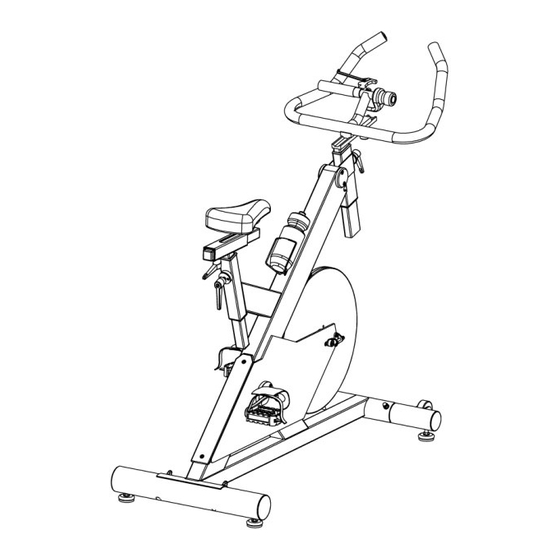
Spin Bike
Hardware Identifier
Assembly Instructions
IC 1
Parts list
Exploded Diagram
Warranty
MODEL
IC 1
Retain This
Manual for
Reference
02-2015
OWNER'S
MANUAL
255 Airport Cir., Corona, CA 92880
Tel:(877) 738-1729 Fax: (714) 738-1728
www.inspirefitness.net
Advertisement
Table of Contents

Related Manuals for Inspire IC 1


Summary of Contents for Inspire IC 1
- Page 1 NOTE: Please read all instructions carefully before using this product. Table of Contents Safety Notice Spin Bike Hardware Identifier Assembly Instructions IC 1 Parts list Exploded Diagram Warranty MODEL IC 1 Retain This Manual for Reference 02-2015 OWNER’S MANUAL 255 Airport Cir., Corona, CA 92880 Tel:(877) 738-1729 Fax: (714) 738-1728 www.inspirefitness.net...
-
Page 2: Table Of Contents
Exploded Diagrams ........... 17 Warranty ..............18 Before You Begin Thank you for selecting the INSPIRE SPIN BIKE. For your safety and benefit, read this manual carefully before using the machine. As a manufacturer, we are committed to providing you complete customer satisfaction. -
Page 3: Important Safety Notices
IMPORTANT SAFETY NOTICE PRECAUTIONS This exercise machine is built for optimum safety. However, certain precautions apply whenever you operate a piece of exercise equipment. Be sure to read the entire manual before you assemble or operate your machine. In particular, note the following safety precautions: 1. -
Page 4: Warning Label Placement
Warning Label Placement The warning labels have been placed on the unit in the locations shown. If the labels are missing or illegible, please call customer service at 1-877-738-1729 for replacements. Apply the labels in the location shown. PAGE 4... -
Page 5: Contents Of Packaging
Contents of Packaging PAGE 5... -
Page 6: Hardware Pack
Hardware Pack (11)M10x20 , 1PCS (54)M8x70 , 4PCS , (49)Ø8 4PCS (10)M10x30 , 1PCS , (50)M8 4PCS (98)5#,1PCS (99)1PCS ( ) Ø10 , 1PCS NOTE: The following parts are not drawn to scale. Please use your own ruler or scale to measure components. -
Page 7: Assembly Instructions
Step 1 Install the Rear Stabilizer(21) onto the Main Frame (12) using 2-M8 Bolts (54), 2-M8 Washers (49), and 2-M8 Nuts (50). PAGE 7... - Page 8 Step 2 Install the Front Stabilizer (16) onto the Main Frame (12) using 2-M8 Bolts (54), 2-M8 Washers (49), and 2-M8 Nuts (50). PAGE 8...
- Page 9 Step 3 Attach the Left Pedal (17) to the Left Crank (20). Turn the threads COUNTERCLOCKWISE in order to install the Left Pedal(17). PAGE 9...
- Page 10 Step 4 Attach the Right Pedal (27) to the Right Crank (26). Turn the threads CLOCKWISE in order to install the Right Pedal(27). PAGE 10...
- Page 11 Step 5 Insert the Handlebar Tube (2) into the Main Frame (12). Thread the L-Handle Handle (11) into the Main Frame (12) to secure the Handlebar Tube (2). PAGE 11...
- Page 12 Step 6 Attach the Handlebars (1) from the top and use the flat washer (9) and the L- Handle(10) to secure the Handle Bars (1) to the Frame. PAGE 12...
- Page 13 Step 7 Attach the Seat(37) to the Adjustable Seat Tube(36) and use the handle under the seat to secure the seat. PAGE 13...
- Page 14 Step 8 Attach the Computer Bracket (41) onto the Handlebars (1). Slip the Computer(40) into the Computer Bracket (41). Secure the Bracket (41) by tightening the M3.5 screw until the Bracket (41) is tight on the Handlebars (1). Attach the Lower Computer Wire (33) to the Handlebar Computer Cable (38). Connect the Handlebar Computer Cable (38) to the Console (40).
-
Page 15: Console Instructions
This unit is equipped with a Telemetric Heart Rate transmitter that allows the user to monitor their heart rate while wearing a Chest Strap. A Chest Strap is included with this unit. For any questions please contact Inspire by calling (877) 738-1729. BASIC OPERATION •... -
Page 16: Parts List
Parts List Item Part No. Part Description BC481-881-001 Handlebars BC480-300-003 Handlebar Tube Assembly 0242-060-31 Handlebar Tube Sleeve, Upper BC480-561-014 Pressure Peg Nut BC480-300-004 Handle Support Assembly A890-881-011 Handlebar Tube Sleeve, Lower BC480-561-015 Belt Tension Bracket Assembly BC481-881-003 Belt Cover 0116-210-005 Flat Washer B465-561-011 L-Handle, Long... -
Page 17: Exploded Diagrams
Exploded View 49 50 PAGE 17... -
Page 18: Warranty
DAMAGES, SO THE ABOVE LIMITATIONS OR EXCLUSION MAY NOT APPLY TO YOU. This Warranty gives you specific legal rights and you may also have other rights that may vary from state to state. This is the only express warranty applicable to FG1’s “Inspire”...
Need help?
Do you have a question about the IC 1 and is the answer not in the manual?
Questions and answers