Advertisement
NOTE:
Please read all
instructions carefully
before using this
product.
Table of Contents
Safety Notice
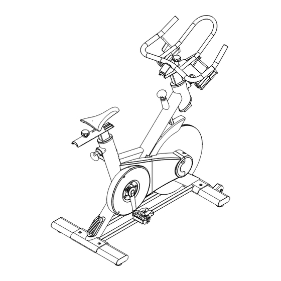
Indoor Cycle
Hardware Identifier
Assembly Instructions
IC 2
Parts list
Exploded Diagram
Warranty
MODEL
IC 2
Retain This
Manual for
Reference
11-2015
OWNER'S
MANUAL
255 Airport Cir., Corona, CA 92880
Tel:(877) 738-1729 Fax: (714) 738-1728
www.inspirefitness.com
Advertisement
Table of Contents

Related Manuals for Inspire Indoor Cycle IC 2


Summary of Contents for Inspire Indoor Cycle IC 2
- Page 1 NOTE: Please read all instructions carefully before using this product. Table of Contents Safety Notice Indoor Cycle Hardware Identifier Assembly Instructions IC 2 Parts list Exploded Diagram Warranty MODEL IC 2 Retain This Manual for Reference 11-2015 OWNER’S MANUAL 255 Airport Cir., Corona, CA 92880 Tel:(877) 738-1729 Fax: (714) 738-1728 www.inspirefitness.com...
-
Page 2: Table Of Contents
Exploded Diagram ............. 15 Warranty ..............16 Before You Begin Thank you for selecting the INSPIRE INDOOR CYCLE. For your safety and benefit, read this manual carefully before using the machine. As a manufacturer, we are committed to providing you complete customer satisfaction. -
Page 3: Before You Begin
IMPORTANT SAFETY NOTICE PRECAUTIONS This exercise machine is built for optimum safety. However, certain precautions apply whenever you operate a piece of exercise equipment. Be sure to read the entire manual before you assemble or operate your machine. In particular, note the following safety precautions: 1. - Page 4 PAGE 4...
-
Page 5: Warning Label Placement
Warning Label Placement The warning label has been placed on the unit at the location shown. If the label is missing or illegible, please call customer service at 1-877-738-1729 for replacements. Apply the labels in the locations shown. PAGE 4... -
Page 6: Contents Of Packaging
Contents of Packaging STEP1&2 Part# 42 (4pcs) Part# 39 (4pcs) Part# 43 (4pcs) STEP3 Part# 30 (1pcs) Part# 31(1pcs) 1pcs TO O L PAGE 5... -
Page 7: Hardware Pack
Hardware Pack STEP1&2 Part# 42 (4pcs) Part# 39 (4pcs) Part# 43 (4pcs) STEP3 Part# 30 (1pcs) Part# 31(1pcs) 1pcs TOOL NOTE: The following parts are not drawn to scale. Please use your own ruler or scale to measure components. PAGE 6... -
Page 8: Assembly Instructions
REAR FRONT Step 1 Install the Rear Stabilizer (3) onto the Main Frame (1) using 2-M8 Bolts (39), 2-M8 Washers (42), and 2-M8 Nuts (43). Install the Front Stabilizer (2) onto the Main Frame (1) using 2-M8 Bolts (39), 2-M8 Washers (42), and 2-M8 Nuts (43). - Page 9 Step 2 Insert the Handlebar Post (26) into the front of the Main Frame (1). Lock down or loosen the Handlebar Post (26) by threading the Pop Pin (16). PAGE 8...
- Page 10 Step 3 Insert the Handlebars (7) into the Lower Handlebar Post (26). Attach the Handlebar Slider End Cap (30) using 2-M4 Bolts (31). PAGE 9...
- Page 11 Step 4 Attach the Left Pedal (20L) to the Left Crank (19L). Turn the threads COUNTERCLOCKWISE to install the Left Pedal(20L). PAGE 10...
- Page 12 Step 5 Attach the Right Pedal (20R) to the Right Crank (19R). Turn the threads CLOCKWISE to install the Right Pedal(20R). PAGE 11...
-
Page 13: Maintenance
Maintenance Monthly Maintenance The adjustment tubes should be lubricated monthly to ensure smooth adjustability. Raise the Seat Post and Handlebar Post to their highest positions. Apply WD40 or a similar spray lubricant at locations A, B, D, and E. Rub the lubrication with a soft cloth. -
Page 14: Parts List
Parts List Item # Part No. Description BC497-200-000 Main Frame Weldment BC497-330-002PZ Front Stabilizer BC497-330-001PZ Rear Stabilizer BC496-561-003PZ Flywheel Assembly Inner Shroud BC497-881-007PZ Outer Shroud BC497-881-001PZ BC497-881-008 Handle Bar BC497-560-001 Seat Post Weldment BC497-560-002PZ Seat Post Free Rail BC495-401-001A Seat Pad BC497-561-003 Friction Plate Housing Nut BC497-881-011PZ... - Page 15 0110-412-599 Hex Flange Nut BC20-221-41 Plastic Cap BC497-881-003PZ Shroud, L BC497-881-005 Adjustable Rail End Cap 0113-204-109 Hex Bolt BC495-881-013APZ Lower Plastic Sleeve BC496-561-010APZ Crankshaft Assembly 0200-300-086 Crankshaft Bearing BC497-561-005 Crankshaft Bearing Spacer BC497-881-002PZ Right Shroud Cap BC496-561-014 Crankshaft Locknut BC497-560-004PZ Handlebar Rail, Free 0113-310-259 Hex Bolt...
-
Page 16: Exploded Diagram
Exploded View 31 30 31 30 27 23 PAGE 15... -
Page 17: Warranty
DAMAGES, SO THE ABOVE LIMITATIONS OR EXCLUSION MAY NOT APPLY TO YOU. This Warranty gives you specific legal rights and you may also have other rights that may vary from state to state. This is the only express warranty applicable to FG1’s “Inspire”...
Need help?
Do you have a question about the Indoor Cycle IC 2 and is the answer not in the manual?
Questions and answers