Table of Contents
Advertisement
Quick Links
INSTALLATION & OPERATING INSTRUCTIONS
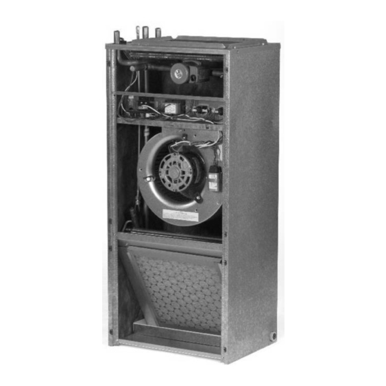
VERTICAL WALL MOUNT AIR HANDLER
MODEL
(INCLUDING HEATER MODEL #) ________________________________
SERIAL #____________________________________________________
INSTALLER __________________________________________________
INSTALLATION DATE _________________________________________
These instructions should be retained and kept adjacent to the unit for future use
IO-123090-GFW-020113
©2013 AirMark
GFW SERIES
HIGH EFFICIENCY X13
(HYDRONIC)
373 Atascocita Rd.
Humble, TX 77396
Phone 800.423.9007
Fax 281.441.6510
www.airmark-ac.com
Advertisement
Table of Contents

Summary of Contents for Airmark GFW SERIES
- Page 1 GFW SERIES INSTALLATION & OPERATING INSTRUCTIONS HIGH EFFICIENCY X13 VERTICAL WALL MOUNT AIR HANDLER (HYDRONIC) MODEL (INCLUDING HEATER MODEL #) ________________________________ SERIAL #____________________________________________________ INSTALLER __________________________________________________ INSTALLATION DATE _________________________________________ These instructions should be retained and kept adjacent to the unit for future use 373 Atascocita Rd.
-
Page 2: Safety Instruction
Safety Instruction Airmark will not be responsible for damages caused due to modification of the unit to operate Potential safety hazards are alerted using with alternative power sources. symbol. The symbol is used in conjunction with terms that indicate the intensity of the hazard. -
Page 3: Installation
MUST be trapped or sealed. Failure to do so will result in condensate overflow It is recommended that wherever supply and return from the drain pan. Airmark will NOT be air sheet metal ducts pass through unconditioned responsible for any damages resulting from failure areas, they be insulated to prevent excessive heat to follow these instructions. -
Page 4: Metering Device
3) The wrench used to clasp the nut should be turned in a counter-clockwise direction to unscrew the nut. Metering Device Airmark coils are available with two kinds of 4) Slide the 13/16 nut over the line set and metering devices flowrator TXV. - Page 5 TXV bulb installation in the horizontal plane. The TXV sensing bulb SHOULD be mounted using the metal clamp provided. In order to obtain a good temperature reading and correct superheat control, IO-123090-GFW-020113 - 5 - ©2013 AirMark...
- Page 6 Some Airmark coils come with a Schrader valve on Field – Installed Expansion Valve Coils the suction line. If a Schrader port is present...
-
Page 7: Electrical Installation
After the thermostat is satisfied, the ON position (left two pins). blower will continue to stay energized for a minimum of 30 secs. This helps maximize heating efficiency. IO-123090-GFW-020113 - 7 - ©2013 AirMark... - Page 8 MUST be purged of air prior to thermostat on heat. Raise the temperature starting the pump. Failure to do so could result in setting to activate the circulating pump pump damage. Airmark will not be responsible for IO-123090-GFW-020113 - 8 - ©2013 AirMark...
- Page 9 Tap 2 632 600 552 temperatures. Table 2 below shows the CFM that Tap 1 449 421 395 should be achieved at various external static pressures Table 2. CFM delivered at various external statics IO-123090-GFW-020113 - 9 - ©2013 AirMark...
- Page 10 6) Lubrication- Direct drive blower motors are will be located either in the equipment or in the equipped with permanently lubricated bearings return air duct system upstream of the and do not require further lubrication. IO-123090-GFW-020113 - 10 - ©2013 AirMark...
- Page 11 76%): For mild climates: BTU INPUT=structure’s heat loss x 1.51. For colder climates: BTU f. Look for restrictions in heating system from water INPUT=structure's heat loss x 1.58. heater to fan coil. Some water heaters are supplier IO-123090-GFW-020113 - 11 - ©2013 AirMark...
- Page 12 CMR 248 Massachusetts State Plumbing Code and/or Massachusetts Fuel Gas Code. These codes require the use of an optional pump timer to circulate the hydronic loop independent of the thermostat. IO-123090-GFW-020113 - 12 - ©2013 AirMark...
- Page 13 Wiring diagram for GFW models IO-123090-GFW-020113 ©2013 AirMark...


Need help?
Do you have a question about the GFW SERIES and is the answer not in the manual?
Questions and answers