Table of Contents
Advertisement
Certified technicians or those individuals
!
WARNING
meeting the requirements specified by
NATE may use this information. Property
and product damage or personal injury hazard may occur
without such background.
Disconnect ALL power sources prior to
WARNING
!
servicing. Failure to do so may cause
personal injury or property damage.
Product
!
WARNING
to permit installation in accordance
with local and national building codes.
It is the installer's responsibility to ensure that product is
installed in strict compliance with national and local codes.
Manufacturer takes no responsibility for damage (personal,
product or property) caused due to installations violating
regulations. In absence of local/state codes, refer to National
Electric Code: NFPA 90A & 90B Uniform Mechanical Code.
When this unit is installed in an enclosed
!
WARNING
area, such as a garage or utility room with
any Carbon Monoxide producing devices
(i.e. automobile, space heater, water heater etc.) ensure that
the enclosed area is properly ventilated.
Only
!
CAUTION
accessories
installing or modifying this unit unless it is
so noted in these instructions. Some localities may require
a licensed installer/service personnel.
Unit
WARNING
!
installations.
The unit is designed for operation with
!
WARNING
120V, single phase, 60 Hz power supply.
Aspen
damages caused due to modification of the unit to operate
with alternative power sources.
IO-123163 Effective 01-14-2016
1. Safety Instruction
Potential safety hazards are alerted using the following symbols. The symbol is used in conjunction with terms
that indicate the intensity of the hazard.
WARNING
!
!
CAUTION
designed
and
manufactured
factory
authorized
kits
should
be
used
is
not
approved
for
will
not
be
responsible
INSTALLATION GUIDE
GFT/GFS Series - Cased/Uncased
Ceiling Mount Hydronic Heat Dx Cool
Air Handler
This symbol indicates a potentially hazardous situation, which if not avoided,
could result in serious injury, property damage, product damage or death.
This symbol indicates a potentially hazardous situation, which if not avoided,
may result in moderate injury or property damage.
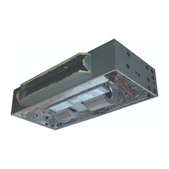
2. Introduction
The GFS/T Series air handlers are versatile horizontal ceiling mount
units. These air handlers have the following standard features:
I. Application Versatility
Louvered ceiling access panel has separate frame that attaches to
ceiling joists. Solid access panel available for use with end return
installations. Compatible with most brands of air conditioners or heat
pumps.
II. Motor
Constant torque EC motor allows motor speed control with embedded
software. Blowers are mounted on a plate so they can be easily
removed for service.
III. Cabinet (GFT Only)
Sturdy, fully insulated galvanized steel cabinet with painted front
panels. Knockout for duct return.
IV. Electronic Circuit Board
Electronic circuit board provides 30 secs ON/OFF blower time delay,
extracting more heat/cool from the coil.
and
when
V. DX Coil
High efficiency rifled copper tubes/enhanced aluminum fins provide
maximum heat transfer. All coils immersion tested at 500 psi then
outdoor
nitrogen pressurized and factory sealed for maximum reliability.
Liquid-line Schrader allows pre-installation pressure testing.
Available with either orifice or TXV metering device. Field-installable
bolt-on TXVs are also available. Primary & secondary condensate
drain. All drain connections are 3/4" MPT. Access door allows for coil
cleaning. Certified for use with either R22 or R410a.
for
VI. Warranty
One year limited parts warranty.
1
Advertisement
Table of Contents

Related Manuals for Airmark GFT Series

Summary of Contents for Airmark GFT Series
- Page 1 INSTALLATION GUIDE GFT/GFS Series - Cased/Uncased Ceiling Mount Hydronic Heat Dx Cool Air Handler 1. Safety Instruction Potential safety hazards are alerted using the following symbols. The symbol is used in conjunction with terms that indicate the intensity of the hazard. WARNING This symbol indicates a potentially hazardous situation, which if not avoided, could result in serious injury, property damage, product damage or death.
-
Page 2: Installation Preparation
Clearances Fig 4D-1. Condensate Drain Trap The GFT series of horizontal ceiling mount air handlers are designed for zero clearance installation on the sides and back. Since coil is upstream of the blower, all CAUTION drains MUST be trapped or sealed. - Page 3 5. Installation Ensure that the unit is adequately sized. CAUTION The tonnage of the outdoor unit should never exceed the tonnage of this unit. The coil was manufactured with a dry WARNING nitrogen pre-charge. Release the pressure through the Schrader valve test port prior to installation.
- Page 4 7B. Bottom Return 1. A bottom return installation requires a louvered panel. 6. Reinstall the components removed prior to mounting the enclosure. 7. Connecting Ducting 1. Secure the supply air ducting to the duct flange of the air handler. Canvas connectors are recommended for reducing potential noise transmission.
-
Page 5: Installation
II. Piston Replacement Use Piston sizes recommended by the CAUTION outdoor unit manufacturer whenever Note: Photos are for basic illustration purposes only. Actual possible. The piston should be sized equipment configuration may differ from that shown. according to the capacity of the outdoor unit. During some installations, a piston change may be required. - Page 6 II-5. Pull the piston out using The sensing bulb and TXV body MUST WARNING a small wire or pick. Verify the be protected from overheating during piston size (size is typically brazing. The sensing bulb and TXV body stamped on the body of the must be covered using a quench cloth or wet cloth when piston - Fig 8A-2).
- Page 7 II. TXV Bulb Vertical Mounting III-6. Remove the additional Teflon O-ring seal from the box and place on the shoulder just The TXV sensing bulb should inside the TXV inlet port. Screw be mounted in a horizontal the nut attached to the stub-out plane in relation to the suction/ portion of the flowrator body onto vapor line.
-
Page 8: Connecting Refrigerant Lines
9. Connecting Refrigerant Lines 10. Leak Check Following outdoor unit manufacturer instructions 1. Release nitrogen holding recommendations, charge the system with dry nitrogen to a maximum pressure of 150 PSIG. charge depressing Shrader Valve at the liquid line connection on the air handler. If no gas releases from the 2. - Page 9 The aquastat (AQ) jumper must be in the Transformer CAUTION OFF position at all times, except for when 120VAC 24VAC (Fig 11-3). an aquastat is used. If the jumper is moved to the ON position without installing an aquastat, the blower will not be energized.
-
Page 10: Condensate Drain
12. Condensate Drain 14. System Charging 1. Select desired condensate drain openings according to air handler An improperly charged system may cause orientation. Both Primary and Secondary outlets can be used. CAUTION degradation in system performance and 2. Pipe condensate system using proper PVC fittings. damage the compressor. -
Page 11: Purging The System
15. Adjustment of Heat Anticipator Purging The System After all connections are made, start-up and checkout must be performed before proper evaluation of the entire system can be 1. Open air vent and allow water heater to fill with water. Close air made. -
Page 12: Operation And Maintenance
17. Checking Air Flow/Temperature Rise Method 5. Periodic Checkup and Service- This product is designed to provide many years of dependable, trouble-free comfort when properly Turn on power supply. Set thermostat fan switch to on. Set the maintained. Proper maintenance will consist of annual check-ups cooling indicator to maximum, heating to minimum. -
Page 13: Common Problems And Solutions
20. Common Problems and Solutions 1. Noisy Pump System may not be totally purged of air. Purge the system again as described in the start up section above. 2. T&P valve on water heater weeps This normally occurs when a backflow preventer has been installed in the cold water supply line to the water heater. - Page 14 Fig. 20-1 Wiring diagram for GFS/GFT models IO-123163 Effective 01-14-2016...
- Page 15 Massachusetts Applicable Installation Diagram Massachusetts Applicable Installation Diagram IO-123163 Effective 01-14-2016...
- Page 16 373 Atascocita Rd. Humble, TX 77396 Phone: 281.441.6500 Toll Free: 800.423.9007 Fax: 281.441.6510 www.airmark-ac.com Revised 10/29/2015. Subject to change without notice and without incurring obligation. © Copyright 2015 AirMark. All Rights Reserved IO-123163 Effective 01-14-2016...
Need help?
Do you have a question about the GFT Series and is the answer not in the manual?
Questions and answers