Table of Contents
Advertisement
INSTALLATION INSTRUCTIONS
Split System Heat Pump & Air Conditioner
RECOGNIZE THIS SYMBOL AS AN INDICATION OF IMPORTANT SAFETY INFORMATION
WARNING
These instructions are intended as an aid to qualified
licensed service personnel for proper installation, adjust-
ment and operation of this unit. Read these instructions
thoroughly before attempting installation or operation.
Failure to follow these instructions may result in improper
installation, adjustment, service or maintenance possibly
resulting in fire, electrical shock, property damage,
personal injury or death.
Please read carefully and keep in a safe place for future reference by a serviceman.
14 SEER
14 SEER
1.5-5 Tons
R410A
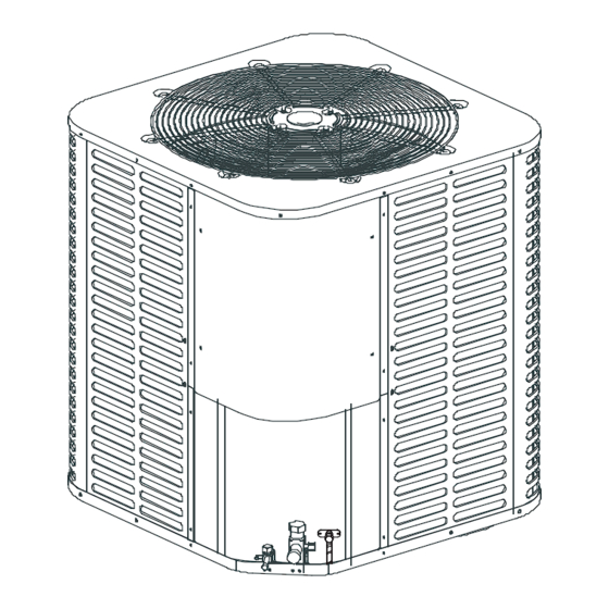
NOTE: Appearance of unit may vary.
DO NOT DESTROY THIS MANUAL
Advertisement
Table of Contents

Related Manuals for Ameristar M4HP40 Series


Summary of Contents for Ameristar M4HP40 Series
-
Page 1: Installation Instructions
INSTALLATION INSTRUCTIONS 14 SEER 14 SEER Split System Heat Pump & Air Conditioner 1.5-5 Tons R410A NOTE: Appearance of unit may vary. RECOGNIZE THIS SYMBOL AS AN INDICATION OF IMPORTANT SAFETY INFORMATION WARNING These instructions are intended as an aid to qualified licensed service personnel for proper installation, adjust- ment and operation of this unit. -
Page 2: Table Of Contents
TABLE OF CONTENTS 1.0 SAFETY........................3 1.1 INSPECTION....................4 1.2 LIMITATIONS....................4 2.0 GENERAL......................4 3.0 UNIT INSTALLATION....................6 3.1 LOCATION.......................6 3.2 GROUND INSTALLATION................6 3.3 ROOF INSTALLATION..................6 3.4 UNIT PLACEMENT..................6 3.5 UNIT MOUNTING....................7 3.6 FACTORY-PREFERRED TIE-DOWN METHOD..........8 3.7 PRECAUTIONS DURING LINE INSTALLATION..........9 3.8 PRECAUTIONS DURING BRAZING OF LINES..........10 3.9 PRECAUTIONS DURING BRAZING SERVICE VALVE.........10 4.0 INTERCONNECTING TUBING................12 4.1 SUCTION AND LIQUID LINES ..............12... -
Page 3: Safety
This document is customer property and is to remain with this unit. These instructions do not cover all the different variations of systems nor does it provide for every possible contingency to be met in connection with installa- tion. All phases of this installation must comply with NATIONAL, STATE, AND LOCAL CODES. -
Page 4: Inspection
1.1 INSPECTION As soon as a unit is received, it should be inspected for possible damage during transit. If damage is evident, the extent of the damage should be noted on the carrier's delivery receipt. A separate request for inspection by the carrier's agent should be made in writing. -
Page 5: Dimensional Data
AIR DISCHARGE: ALLOW 60” MINIMUM CLEARANCE. AIR INLETS LOUVERED PANELS ALLOW 18” MINIMUM CLEARANCE SERVICE ACCESS ALLOW 24” CLEARANCE NOTE: GRILL APPEARANCE MAY VARY. POWER WIRING SEE DETAIL A CONTROL WIRING DETAIL A 7/8” (22.2mm) KNOCKOUT 1-11/32” (34.5mm) ACCESS VALVE FOR LOW PRESSURE NOTE: ONLY ADOPTED BY HEAT PUMP,... -
Page 6: Unit Installation
3.0 UNIT INSTALLATION 3.1 LOCATION Before starting the installation, select and check the suitability of the location for both the indoor and outdoor unit. Observe all limitations and clearance requirements. The outdoor unit must have sufficient clearance for air entrance to the condenser coil, for air discharge and for service access. -
Page 7: Unit Mounting
The outdoor unit must be connected to the indoor coil using field supplied refrigerant grade copper tubing that is internally clean and dry. Units should be installed only with the tubing sizes for approved system combinations. The refrigerant charge shown in the nameplate is for standard size interconnecting liquid line lengths up to 15 feet. -
Page 8: Factory-Preferred Tie-Down Method
3.6 FACTORY-PREFERRED TIE-DOWN METHOD Step 1: Prior to installing clear pad of debris. IMPORTANT The pad must meet local codes and must be the proper thickness to accommodate fasteners. Step 2: Center and level unit onto pad. Step 3: Using field supplied L-shaped bracket to locate holes on concrete and drill pilot holes which is at least 1/4”... -
Page 9: Precautions During Line Installation
3.7 PRECAUTIONS DURING LINE INSTALLATION 1. Install the lines with as few bends as possible. Care should be taken not to kink or damage copper tubing. Use clean hard drawn copper tubing where no appreciable amount of bending around obstruction is necessary, care must be taken to avoid sharp bends which may cause a restriction. -
Page 10: Precautions During Brazing Of Lines
WEATHERPROOF DISCONNECT POWER SWITCH SUPPLY INDOOR BLOWER COIL Seal opening(s) with permagum or equivalent NOTE:All outdoor wiring must be weather proof Fig.7 Typical Installation 3.8 PRECAUTIONS DURING BRAZING OF LINES All outdoor unit and evaporator coil connections are copper-to-copper and should be brazed with a phosphorous-copper alloy material such as Silfos-5 or equivalent. - Page 11 Connect the refrigerant lines using the following procedure: 1. Remove the cap and Schrader core from both the liquid and suction service valve service ports at the outdoor unit. Connect 40 PSI nitrogen to the liquid line service port. service valve wet rag Fig.8 Heat Protection 2.
-
Page 12: Interconnecting Tubing
10. Replace cap on service ports. Do not remove the flare caps from the service ports except when necessary for servicing the system. 11. Release the refrigerant charge into the system. Open both the liquid and suction valves by removing the plunger cap and with an hex wrench back out counter -clockwise until valve stem just touches the chamfered retaining wall. -
Page 13: Line Sizing
LINE SIZING TABLE 2: SUCTION LINE LENGTH/SIZE VS CAPACITY MULTIPLIER(R410A) 1 1/2 Ton 2 Ton 2 1/2 Ton 3 Ton 3 1/2 Ton 4 Ton 5 Ton Model Size Suction Line Connection Size 3/4" O.D. 3/4" O.D. 3/4" O.D. 3/4" O.D. 3/4"... -
Page 14: Electrical Connections
6.0 ELECTRICAL CONNECTIONS 6.1 GENERAL INFORMATION & GROUNDING Check the electrical supply to be sure that it meets the values specified on the unit nameplate and wiring label. Power wiring, control (Iow voltage) wiring, disconnect switches and over current protection must be supplied by the installer. Wire size should be sized per require- ments. -
Page 15: Removing The Top Panel And Motor
6.3 REMOVING THE TOP PANEL AND MOTOR 1/2” nut NOTE: 5/16” nuts Damage will occur to condenser unit if you remove fan nuts prior to cover removal. Fig.10 COVER AND FAN When motor requires changing follow the steps below: Step 1: Go into electrical panel, disconnect motor power lines. IMPORTANT NOTE Disconnect main power to unit. -
Page 16: Protection Function Introduction
(Heat pump only) 7.3 PROTECTION FUNCTION INTRODUCTION Sensor T3 (condenser pipe temperature) and T4 (outdoor ambient temperature) When open-circuit, compressor, outdoor fan motor and reverse valve will be OFF. T3>143.6° F ,compressor stop working ; T3<125.6° F ,compressor start working. When T4 <... -
Page 17: Checking Refrigerant Charge
7.4.2 When SW3-3 switch is set to “OFF”(See in Fig 11), the mode will start up in any of the following conditions: 1. Compressor operating, when T3 is < 30.2 °F last for 60 minutes; 2.T3 is < 28.4 °F and compressor operating for the first time after connected to the power source. 3. -
Page 18: Maintenance
9.0 WARRANTY Assist owner with processing Warranty cards and/or online registration. 9.1 MAINTENANCE . Dirt should not be allowed to accumulate on the indoor or outdoor coils or other parts in the air circuit. Clean as often as necessary to keep the unit clean. Use a brush, vacuum cleaner attachment, or other suitable means. -
Page 19: Control Wiring For A/C Units
10.1 CONTROL WIRING FOR A/C UNITS PLUG PLA TE PLUG PLA TE GROUND GROUND LINE VOL T AGE F ACT OR Y S T ANDARD FIELD INST ALLED F ACT OR Y OPTIONAL BLACK BLACK LO W VOL T AGE F ACT OR Y S T ANDARD FIELD INST ALLED F ACT OR Y O PTIONAL... -
Page 20: Control Wiring For H/P Units
10.2 CONTROL WIRING FOR H/P UNITS COMPRESSOR CONTACTOR CRANKCASE HEATER COMP COMPRESSOR DEFROST CONTROL AMBIENT TEMPERATURE PIPE TEMPERATURE HIGHT PRESSURE CUT-OUT CONTROL LOW PRESSURE CUT-OUT CONTROL OUTDOOR FAN MOTOR RC 1 RUN CAPACITOR 1 RC 2 RUN CAPACITOR 2 RC 3 RUN CAPACITOR 3 REVER SING VALVE... -
Page 21: Electrical Data
ELECTRICAL DATA: Minimum Circuit Ampacity(A) Maximum Circuit Protector(A) Model 12.0 18AC 17.6 24AC 30AC 18.7 36AC 21.9 42AC 24.1 48AC 29.0 60AC 28.0 11.9 18HP 17.5 24HP 18.7 30HP 21.9 36HP 24.1 42HP 29.0 48HP 60HP 34.7 NOTES: AC: Air Conditioner; HP: Heat Pump Piston Size / TXV If Preinstalled Piston... - Page 22 REFRIGERANT CHARGE FOR AC SYSTEM 14 SEER R410A AC Charge Chart 1.5 TON Outdoor Ambient Temperature(℉) Cooling Mode Liquid Pressure at Small Service Valve(psig) 14 SEER R410A AC Charge Chart 2 TON Outdoor Ambient Temperature(℉) Cooling Mode Liquid Pressure at Small Service Valve(psig) 14 SEER R410A AC Charge Chart 2.5 TON Cooling Outdoor Ambient Temperature(℉)
-
Page 23: Refrigerant Charge For Hp System
14 SEER R410A AC Charge Chart 4 TON Cooling Outdoor Ambient Temperature(℉) Mode Liquid Pressure at Small Service Valve(psig) 14 SEER R410A AC Charge Chart 5 TON Cooling Outdoor Ambient Temperature(℉) Mode Liquid Pressure at Small Service Valve(psig) REFRIGERANT CHARGE FOR HP SYSTEM. 14 SEER R410A HP Charge Chart 1.5 TON (Cooling mode) Cooling Outdoor Ambient Temperature(℉) - Page 24 14 SEER R410A HP Charge Chart 2.5 TON (Cooling mode) Outdoor Ambient Temperature(℉) Cooling Mode Liquid Pressure at Small Service Valve(psig) 14 SEER R410A HP Charge Chart 3 TON (Cooling mode) Outdoor Ambient Temperature(℉) Cooling Mode Liquid Pressure at Small Service Valve(psig) 14 SEER R410A HP Charge Chart 3.5 TON (Cooling mode) Outdoor Ambient Temperature(℉) Cooling...
-
Page 25: Troubleshooting
TABLE 4. Troubleshooting SYSTEM FAULTS REFRIGERANT CIRCUIT Head Pressure Too High Head Pressure Too Low Suction Pressure Too High Suction Pressure Too Low Liquid Refrig. Floodback (TXV) I.D. Coil Frosting Compressor Runs Inadequate or No Cooling/Heating ELECTRICAL Compressor & O.D. Fan Won’t Start Compressor Will Not Start But O.D. - Page 26 Base Limited Warranty Single Phase R-410A Outdoor Units, Single Phase R-22 Outdoor Units, Air Handlers, Subject to the terms and conditions of this limited warranty, Ingersoll Rand (“Company’) extends a limited warranty against manufacturing defects for the product(s) Table 1 attached hereto (“Products’) that are installed in a residential/multi-family application (personal, family or household purposes) under normal use and maintenance in the United States and Canada.
- Page 27 TABLE 1: Warranty Time Periods COVERAGE TERMS FOR RESIDENTIAL APPLICATIONS : Pursuant to the Ingersoll Rand (“Company”) lim - ited warranty terms and conditions, the following Products are covered for the base time periods as stated below (“Base Limited Warranty Period’). If registered, the Base Limited Warranty Periods for certain Products will be extended as stated below (“Registered Limited Warranty Period”).
- Page 28 TR-MD14U-035AW 2020001C0543 V1.0...
Need help?
Do you have a question about the M4HP40 Series and is the answer not in the manual?
Questions and answers