
Subscribe to Our Youtube Channel
Related Manuals for AirTek PCMH45

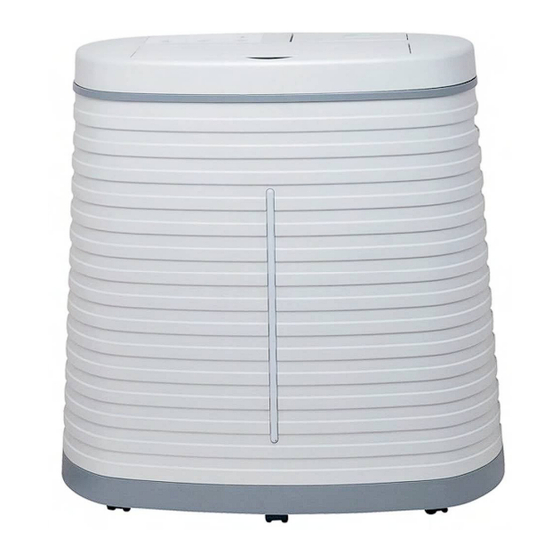
Summary of Contents for AirTek PCMH45
- Page 1 HUMIDIFIER SERVICE MANUAL CAUTION: Before servicing the unit, read the “Safety Precautions” in this manual. Only for authorized service. MODEL NO.: PCMH45...
-
Page 2: Table Of Contents
CONTENT 1. Preface 1.1. Safety Precautions 1.2. Insulation Resistance Test 1.3. Specifications 1.4. Features 1.5. Warning & Safety Rules 1.6. Operations 1.7. Cleaning & Maintenance 2. Disassembly Instructions 2.1 How To Change Carbon Filter 2.2 How To Change PCBA 2.2.1 Top cap & air flow direction part 2.2.2 PCBA Box Cover &... -
Page 3: Preface
Measure the resistance value with an ohm meter between the jumper lead and each exposed metallic part on the equipment at all MODES (except POWER OFF). The value should be over 1 MΩ. 1.3 Specifications MODELS PCMH45 ITEMS Power Supply 220-240V, 50Hz Input (W) Running Current (A) 0.3A... -
Page 4: Features
1.4 Features Very powerful airflow: up to 500 m /hr or 294 CFM. Carbon filter for air cleaning. Adjustable humidification level to your comfort. - L (low) the unit will keep the humidity level around the 30% RH - M (medium) the unit will keep the humidity level around the 45% RH - H (high) the unit will keep the humidity level around the 60% RH - C (continuously) the unit will work continuously... - Page 5 DO NOT let children play with the packaging, for example plastic Bags, as there is a danger of suffocation. Children should be supervised to ensure that they do not play with the appliance. If the unit is damaged or it malfunctions, do not continue to operate it. ...
-
Page 6: Operations
1.6 Operations Control Panel: Operation Instructions: FILL WATER:... -
Page 8: Cleaning & Maintenance
1.7 CLEANING & MAINTENANCE... - Page 9 4. Cleaning inside and outside Use a soft cloth with mild soap to clean the outside and other inside parts with possible scale deposits of your humidifier. Never use aggressive detergents to clean the unit. In order to extend the lifetime of your humidifier we recommend to clean the unit inside, outside and the water reservoir regular.
-
Page 10: Disassembly Instructions
2. DISASSEMBLY INSTRUCTIONS WARNING – Before the following disassembly, POWER is set to OFF and disconnected the power cord. 2.1 How To Change Carbon Filter Use screw driver to remove 1 Remove the air inlet grille. Get the carbon filter. SS screw with head (ST4*12) on the air inlet grille. -
Page 11: How To Change Pcba
2.2 How To Change PCBA 2.2.1. Top cap & air flow direction part Unlock and open the top cap. Take out the air flow direction part. 2.2.2. PCBA Box Cover & Wiring Holder Use screw driver to remove Use screw driver to remove Use screw driver to remove 2pcs SS screw... -
Page 12: Pcba Wiring Connection
2.2.4 PCBA Wiring Connection Unplug the wiring connection. Unplug the wiring connection. electric soldering iron to unplug the wiring connection to get the PCBA. 2.2.5 Wiring Color Connection Wiring color connection refers to part 4.2 Wiring Color Description. -
Page 13: How To Change Fan Motor
2.3 How To Change Fan Motor Open the top cap and take out the air flow direction part follow the procedure 2.2.1 Remove the PCBA box cover and wiring holder follow the procedure 2.2.2 Remove the PCBA follow the procedure 2.2.3 2.3.1 Wiring Connection Between The PCBA And Fan Motor Use the electric soldering iron to... -
Page 14: Split Pin & Wheel Gear Of Synchronous Motor
2.3.4 Split pin & wheel Gear Of Synchronous Motor Unlock and take out the split pin of Take out the wheel gear of syn. syn. motor. motor. 2.3.5 Motor Shroud Use screw driver to remove 8pcs SS screw with head (ST4*12) on motor shroud. -
Page 15: Wiring Cap
2.3.7 Wiring Cap Remove the wiring cap of earth wire. Remove the wiring cap (below picture shown). Note: connection between capacitor and the motor. 2.3.8 Fan Blade & Motor Remove 1pc SS nut (M8) on the Take out the fan blade Use screw driver to remove fan blade. -
Page 16: How To Change Drum Motor
2.4 How To Change Drum Motor Open the top cap and take out the air flow direction part follow the procedure 2.2.1; Remove the PCBA box cover and wiring holder follow the procedure 2.2.2; Remove the PCBA follow the procedure 2.2.3; Remove the water wheel and water reservoir follow the procedure 2.3.2 and 2.3.3;... -
Page 17: How To Change To New Water Wheel
2.5 How To Change To New Water Wheel Open the top cap and take out the air flow direction part follow the procedure 2.2.1; Remove the old water wheel follow the procedure 2.3.2 2.5.1 Old Front Bearing Bracket And Old Spring Use screw driver to remove Use screw driver to remove 4pcs... -
Page 18: How To Change To New Motor Shroud
2.6 How To Change To New Motor Shroud Open the top cap and take out the air flow direction part follow the procedure 2.2.1 Remove the PCBA box cover and wiring holder follow the procedure 2.2.2 Remove the PCBA follow the procedure 2.2.3 Remove the wiring connection between the PCBA and fan motor follow the procedure 2.3.1 Remove the water wheel follow the procedure 2.3.2 Remove the water reservoir follow the procedure 2.3.3... -
Page 19: Troubleshooting Guide
3. TROUBLESHOOTING GUIDE 3.1 Outside Dimensions Width: 745 mm (29.3’’) Depth: 440 mm (17.3’’) Height: 750 mm (29.5’’) 3.2 How it works... -
Page 20: Troubleshooting Guide
3.3 Troubleshooting Guide The following troubleshooting guide is intended to address the most common symptoms and is by no means exhaustive. If symptoms persist, call a qualified service provider. Only a certified electrician should complete any electrical work. Unplug and disconnect the appliance from the power source before attempting to troubleshoot any of the following symptoms. -
Page 21: Schematic Diagram
4. SCHEMATIC DIAGRAM 4.1 Wiring Diagram 4.2 Wiring Color Description Power Cord: (1) Brown Live (2) Blue Neutral (3) Green + Yellow Earth (Ground) Main Motor: (1) White High speed (2) Yellow Medium speed (3) Blue Low speed (4) Black Neutral (5) Red to capacitor by end-closed connector... -
Page 22: Exploded View
5. EXPLODED VIEW... - Page 23 NO.64 NO.65 NO.66...
- Page 24 NO.87 NO.88 NO.89...
-
Page 25: Replacement Parts List
6. REPLACEMENT PARTS LIST Sr. ERP PART CODE PART NAME CHINESE QUANTITY 脚轮 Caster 02100135 底座 Base pan 03100886 水箱底轮压片 Tank wheel bracket 03100904 水箱底轮 Water tank caster 03100897 水箱 Water tank 03100885 磁浮挡板 Magnetic float stopper 03100903 磁浮 Magnetic float 03301012 水位传感器... - Page 26 齿轮 Gear 03100895 水管接头 Water inlet connector 03100905 隔板 Motor shroud 03100879 03301307 湿度感应器 Humidity sensor 电源开关 power switch 03301029 开关夹片 power switch holder 03100914 单向同步电机 Synchronized motor 03300130 活性炭滤网 mesh filter 03101222 进风盖 Rear grille 03100883 后壳 Rear cover 03100878 M8螺母...
- Page 27 Valve connector 03101412 橡胶垫 Rubber washer 03200537 菊花垫圈 Washer 03200536 固定螺母7/16"-24 Nut 7/16"-24 03101411 橡胶垫 Ø11 Rubber pad 03200529 外接头 Tap water connector 02100237 水箱组件 Water tank assembly 02100108 过滤组合 EFS-PCMH45 FILTER SET Water wheel assembly & front 水轮组件+前支撑组合 Bracket sets...
Need help?
Do you have a question about the PCMH45 and is the answer not in the manual?
Questions and answers