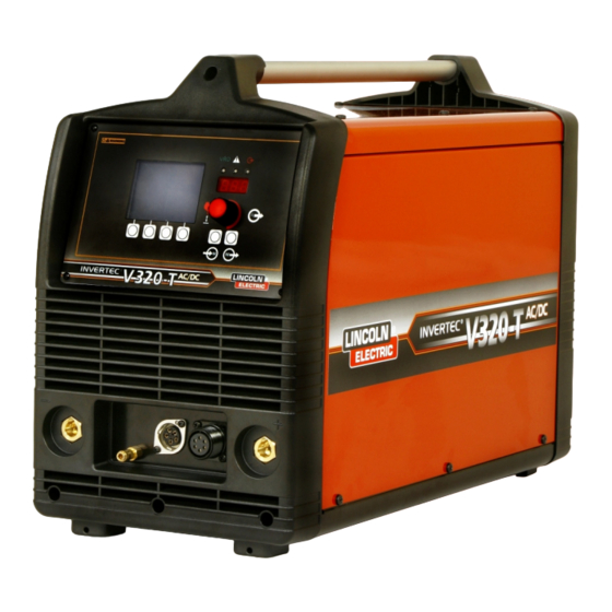
Advertisement
IM2030
11/2009
Rev. 0
®
INVERTEC
V320-T AC/DC
OPERATOR'S MANUAL
MANUALE OPERATIVO
BEDIENUNGSANLEITUNG
MANUAL DE INSTRUCCIONES
MANUEL D'UTILISATION
BRUKSANVISNING OG DELELISTE
GEBRUIKSAANWIJZING
BRUKSANVISNING
INSTRUKCJA OBSŁUGI
KÄYTTÖOHJE
MANUAL DE INSTRUÇÕES
LINCOLN ELECTRIC ITALIA S.r.l
Via Fratelli Canepa 8, 16010 Serrà Riccò (GE), Italia
www.lincolnelectric.eu
Advertisement
Table of Contents

Subscribe to Our Youtube Channel
Summary of Contents for Lincoln Electric INVERTEC V320-T AC/DC
- Page 1 Rev. 0 ® INVERTEC V320-T AC/DC OPERATOR’S MANUAL MANUALE OPERATIVO BEDIENUNGSANLEITUNG MANUAL DE INSTRUCCIONES MANUEL D'UTILISATION BRUKSANVISNING OG DELELISTE GEBRUIKSAANWIJZING BRUKSANVISNING INSTRUKCJA OBSŁUGI KÄYTTÖOHJE MANUAL DE INSTRUÇÕES LINCOLN ELECTRIC ITALIA S.r.l Via Fratelli Canepa 8, 16010 Serrà Riccò (GE), Italia www.lincolnelectric.eu...
- Page 2 été conçu en conformité avec les normes: og er produsert og testet iht. følgende standarder: EN 60974-1, EN 60974-10 (2009) Dario Gatti European Engineering Director Machines LINCOLN ELECTRIC ITALIA S.r.l., Via Fratelli Canepa 8, 16010 Serra Riccò (GE), Italia 12/05...
- Page 3 07/06 Do not dispose of electrical equipment together with normal waste! In observance of European Directive 2002/96/EC on Waste Electrical and Electronic Equipment (WEEE) and its implementation in accordance with national law, electrical equipment that has reached the end of its life must be collected separately and returned to an environmentally compatible recycling facility.
- Page 4 Per ogni futuro riferimento, compilare la tabella sottostante con le informazioni di identificazione equipaggiamento. Modello, Codice (Code) e Matricola (Serial Number) sono reperibili sulla targa dati della macchina. VIELEN DANK! Dass Sie sich für ein QUALITÄTSPRODUKT von Lincoln Electric entschieden haben. •...
- Page 5 Failure to follow the instructions in this manual could cause serious personal injury, loss of life, or damage to this equipment. Read and understand the following explanations of the warning symbols. Lincoln Electric is not responsible for damages caused by improper installation, improper care or abnormal operation.
-
Page 6: Installation And Operator Instructions
EQUIPMENT WEIGHT OVER 30kg: Move this equipment with care and with the help of another person. Lifting may be dangerous for your physical health. CYLINDER MAY EXPLODE IF DAMAGED: Use only compressed gas cylinders containing the correct shielding gas for the process used and properly operating regulators designed for the gas and pressure used. -
Page 7: Remote Control Connection
Connect the gas hose from User Interface Overview and Operation the TIG torch to the gas connector (B) on the front of the machine. If necessary, an extra gas connector for the fitting on the front of the machine is included in the package. - Page 8 The Weld Sequence Diagram shows the various The Parameter Display Section shows the parameters that can be selected and adjusted and selected parameter its display icon and preset their preset values. As the push button/rotary value. To change the value, rotate the push encoder is pressed a triangular shaped flashing button/rotary encoder.
- Page 9 Press and hold the TIG torch trigger to start the sequence. The machine will open the gas valve to start the flow of the shielding gas. After the preflow time, to purge air from the torch hose, the output of the machine is turned ON.
- Page 10 As shown here, again Push button D, E & F: Memory after the TIG torch trigger Operation is quickly pressed and Pressing and releasing the memory location (D) button released from step 3A, it will scroll through memory locations 1 through 10. When is possible to quickly a memory is recalled or saved the memory location press and release the...
-
Page 11: Welding Parameters
Welding Parameters The following parameters are adjustable on the V320-T AC/DC. (See Table B.3) Parameter Range Parameter Parameter Symbol Name Unit Pre-Flow Start Current Peak Finish Current Peak Min. Current Peak Figure B.7 Upslope Rotating the encoder knob will scroll through the setup parameters shown in Table B.4. - Page 12 Setup Menu Parameters Parameter Symbol Selection / * Default Value Parameter Number Description See Figure B.7 Set Up menu Exit • N.A. Reset All Parameters • Start Current Set Unit • • Bi-Level Current 2 Set Unit • • Pulse Background Current Units •...
- Page 13 Lincoln Electric. Before installing the machine, the operator must check the work area for any devices that may malfunction because of electromagnetic disturbances.
-
Page 14: Technical Specifications
Technical Specifications V320-T AC/DC: INPUT Voltage Phase Frequency 230/400 Vac 3 ph 50-60 Hz RATED INPUT and OUTPUT @ 40°C Input Rated Output Current / Voltage / Duty Cycle Input Current @ Rated Output Phase Voltage (Duty Cycle: Based on a 10 min. period) 250 A / 20 V / 100% 10.0 A 280 A / 21.2 V / 60%...


Need help?
Do you have a question about the INVERTEC V320-T AC/DC and is the answer not in the manual?
Questions and answers