Table of Contents
Advertisement
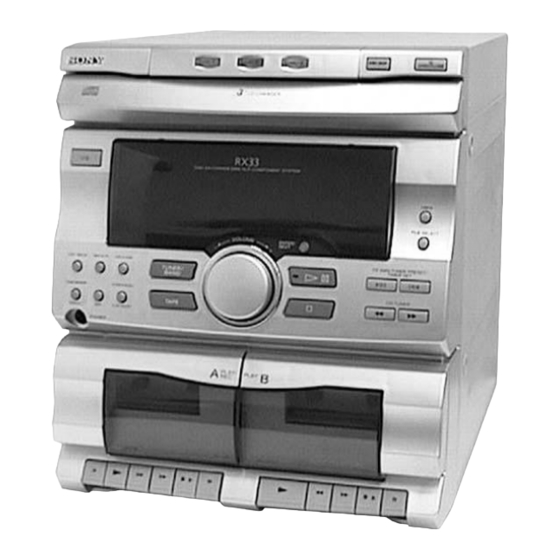
SERVICE MANUAL
HCD-RX33 is the tuner, deck, CD and
amplifier section in MHC-RX33.
The following measured at AC 230 V 50 Hz;
DIN power output (Rated) 25 W + 25 W (6 Ω at 1 kHz, DIN)
Continuous RMS power output (Reference)
35 W + 35W (6 Ω at 1 kHz, 10% THD)
Outputs
PHONES (stereo phone jack) :
accepts headphones of 8 Ω or more
accepts impedance of 6 to 16 Ω
SPEAKER :
CD player section
System
Compact disc and digital audio system
Laser
Semiconductor laser (λ = 780 nm)
Emission duration: continuous
Laser output
Max. 44.6 µW*
*This output is the value measured at a distance
of 200 mm from the objective lens surface on the
Optical Pick-up Block with 7 mm aperture.
Frequency response
20 Hz – 20 kHz (± 0.5 dB)
Wavelength
780 – 790 nm
MICROFILM
HCD-RX33
Model Name Using Similar Mechanism
CD Mechanism Type
CD
Base Unit Type
SECTION
Optical Pick-up Type
Model Name Using Similar Mechanism
TAPE
DECK
Tape Transport
SECTION
Mechanism Type
SPECIFICATIONS
Tape deck section
Recording system
Frequency response
Tuner section
FM stereo, FM/AM superheterodyne tuner
FM tuner section
Tuning range
Antenna
Antenna terminal
Intermediate frequency
AM tuner section
Tuning range
Antenna
Antenna terminals
Intermediate frequency
MINI Hi-Fi COMPONENT SYSTEM
AEP Model
UK Model
HCD-G101
CX3
KSM-213BCM
KSS-213B/S-N
HCD-G101
DECK-A
TK20FX-SW943-800
DECK-B
TK20FX-SW943-800
4 -track 2 -channel stereo
60 – 13,000 Hz (± 3dB), using Sony
TYPE Ι cassette
87.5 – 108.0 MHz
FM lead antenna
75 Ω unbalanced
10.7MHz
531 – 1,602 kHz
AM loop antenna
External antenna terminal
450 kHz
— Continued on next page —
Advertisement
Table of Contents

Related Manuals for Sony HCD-RX33


Summary of Contents for Sony HCD-RX33
- Page 1 HCD-RX33 SERVICE MANUAL AEP Model UK Model HCD-RX33 is the tuner, deck, CD and amplifier section in MHC-RX33. Model Name Using Similar Mechanism HCD-G101 CD Mechanism Type Base Unit Type KSM-213BCM SECTION Optical Pick-up Type KSS-213B/S-N Model Name Using Similar Mechanism...
- Page 2 COMPONENTS IDENTIFIED BY MARK ! OR DOTTED LINE WITH MARK ! ON THE SCHEMATIC DIAGRAMS AND IN THE PARTS LIST ARE CRITICAL TO SAFE OPERATION. REPLACE THESE COMPONENTS WITH SONY PARTS WHOSE PART NUMBERS APPEAR AS SHOWN IN THIS MANUAL OR IN SUPPLEMENTS PUBLISHED BY SONY.
-
Page 3: Table Of Contents
TABLE OF CONTENTS 1. GENERAL ................4 2. DISASSEMBLY 2-1. CD Door ................5 2-2. CD Mechanism Deck ............5 2-3. Front Panel ................. 6 2-4. Main Board and H.P Board ..........6 2-5. CD Tray ................7 2-6. CD Decoder Board ............. 7 2-7. -
Page 4: General
SECTION 1 GENERAL LOCATION OF PARTS AND CONTROLS !• !¶ !º !¡ !™ !£ !¢ !§ !∞ !ª @º @¡ @™ @£ @¢ @∞ @§ @¶ @• !¶ Disc tray FILE SELECT !• DISC 1 button I/u (POWER) button !ª DISC 2 button TUNER MEMORY REPEAT button @º... -
Page 5: Disassembly
SECTION 2 DISASSEMBLY Note : Follow the disassembly procedure in the numerical order given. 2-1. CD DOOR 2 CD door Two claws 1 Pull out the CD tray and remove the CD door with releasing claws into the direction of arrow. 2-2. -
Page 6: Front Panel
2-3. FRONT PANEL 3 Screw (+BVTP 3 × 10) 4 Screw (+BVTP 3 × 10) 5 Two screws (+BVTP 3 × 10) 6 Two screws (+BVTP 3 × 10) 7 Screw (+PTPWH 3 × 10) 1 Connector (CN401) 9 Front panel 7 Screw (+PTPWH 3 ×... -
Page 7: Cd Tray
2-5. CD TRAY 1 Screw (+P 2.6 × 4) 2 Bracket 5 Flat type wire (CN06) 3 Screw (+P 2.6 × 4) 4 Bracket 6 CD tray 2-6. CD DECODER BOARD 1 Two screws (+BVTP 3 × 10) 6 Flat type wire (CN06) 5 Flat type wire (CN01) 7 CD DECODER board 8 Two screw... -
Page 8: Base Unit
2-7. BASE UNIT 4 Screw (+PTPWH 2.6 × 8) 2 Screw (+PTPWH 2.6 × 8) 3 UD-gear 5 UD-Cam 7 Spring 6 Spring 8 Spring 1 Two screws (+KTP 3 × 8) 9 Base unit 2-8. CASSETTE LID (L) / (R) 1 Cassette lid (L) Four claws 2 Cassette lid (R) -
Page 9: Mechanical Adjustments
SECTION 3 SECTION 4 MECHANICAL ADJUSTMENTS ELECTRICAL ADJUSTMENTS DECK SECTION 0 dB=0.775V Precaution 1. Clean the following parts with a denatured alcohol-moistened Demagnetize the record/playback head with a head swab: damagnetizer. record/playback head pinch rollers Do not use a magnetized screwdriver for the adjustments. erase head rubber belts After the adjustments, apply suitable locking compound to the... - Page 10 Turn the adjustment screw and check output peaks. If the peaks After the adjustments, apply suitable locking compound to the do not match for L-CH and R-CH, turn the adjustment screw parts adjusted. so that outputs match within 2 dB of peak. Adjustment Location: Remove the cassette lid before adjustment (See page 8) L-CH...
- Page 11 TUNER SECTION 0 dB=1µV AM Tuning Voltage Adjustment Main board DC voltmeter – Procedure: Set the reception frequency of the unit to 531 kHz. Adjust L108 for 1.2 ± 0.05 V reading on the DC voltmeter. Set the reception frequency of the unit to 1,602 kHz. Confirm that the voltage reading on the DC voltmeter is within 8.0 ±...
- Page 12 FM Tuned Level Adjustment FM RF SSG 75 Ω coaxial Carrier frequency : 98 MHz FM ANTENNA terminal Modulation : AUDIO 1 kHz, 75 kHz (JK101) deviation (100%) : 28 dB (at 75 Ω open) Output level Procedure: Supply a 28 dB 98 MHz signal from the ANTENNA terminal. Tune the set to 98 MHz.
- Page 13 RF Level Check CD SECTION oscilloscope CD DECODER board Note: CD Block is basically constructed to operate without TP (RF) adjustment. Therefore, check each item in order given. CN12 (VC) Use YEDS-18 disc (3-702-101-01) unless otherwise indicated. Use an oscilloscope with more than 10MΩ impedance. Clean the object lens by an applicator with neutral detergent Procedure : when the signal level is low than specified value with the...
-
Page 14: Diagrams
SECTION 5 DIAGRAMS 5-1. CIRCUIT BOARDS LOCATION SW (B) board SW (D) board MOTOR (6P) (S) board SW (C) board MOTOR board DISK board CD DECODER board SW (A) board PANEL board SENSOR board MAIN board H.P board AC POWER board R/P SWITCH board VR board —... -
Page 15: Block Diagrams
HCD-RX33 5-2. BLOCK DIAGRAMS — DECK SECTION — REC/PB EQ AMP IC201 SELECTOR IC301 POWER AMP IC501 PB OUT LINE AMP TAPE B IC302 Q216 Q209 HP901 MUTE R CH MUTE JK303 HEAD SWITCH Q307 Q303 PHONES Q213 BASS BOOST... -
Page 16: Tuner/Cd Section
HCD-RX33 — TUNER/CD SECTION — FM/AM MPX FM FRONT END IC101 FE101 Q101 CF101 CF102 TU L 10.7MHz 10.7MHz FM IF AM/FM RF IF MUTE DECODER 75Ω IF BUFF R CH JK101 ANTENNA Q107 CF104 FM DET MUTE 10.7MHz • RCH is omitted... -
Page 17: Ic Block Diagrams
5-3. IC BLOCK DIAGRAMS IC03 (CD DECORD BOARD) BA5941FP – + – + – LEVEL SHIFT LEVEL SHIFT LEVEL SHIFT – LEVEL SHIFT – – + – – + – MUTE IC02 (CD DECORD BOARD) TC9173P DRIVER SERIAL I/O MUTE CONTROL CONTROL CLOK... - Page 18 IC01 (CD DECORD BOARD) CXA1782BQ – LEVELS 24 SENS – MIRR RF IV AMP1 DFCT 23 C. OUT – 22 XRST RF IV AMP2 21 DATA FE BIAS • IIL DATA RESISTOR • INPUT SHIFT RESISTOR • ADDRESS DECODER 20 XLT •...
- Page 19 IC102 (MAIN BOARD) LA1831 OSC/FMSD AM RF SMET AM HPF AF DET MPX VCO MPX IN R OUT L OUT PL DET MUTE DECORDER RF AMP STEREO SW BUFFER AM IF AM DET STEREO DRIVE TRIG AM/FM IF BUFE COMP PILOT LEVEL TUNING...
- Page 20 IC301 (MAIN BOARD) LC75392 LVROUT RVROUT LVRIN RVRIN LTOUT RTOUT – LTCOM RTCOM LATCH DECODER SHIFT REGISTER VREF CONTROL IC201 (MAIN BOARD) TA8189N METAL TAPE A CH2/A CH2/B /TAPE B – – VREF1 IREF VREF2 – – CH1/A CH1/B METAL GND1 —...
- Page 21 IC602 (PANEL BOARD) BU2092 16 15 14 13 12 11 12 BIT CONTROL SHIFT CIRCUIT REGISTER OUTPUT 12 BIT BUFFER STORAGE (OPEN DRAIN) REGISTER 5 6 7 8 9 — 23 —...
-
Page 22: Ic Pin Function
5-10. IC PIN FUNCTION IC601 µPD780205GF (SYSTEM CONTROL) / PANEL BOARD Pin No. Pin Name Description — POWER OUT Power switch output. ON: H, OFF: L S. MUTE OUT System mute output. ON: H, OFF: L TU. MUTE OUT Tuner mute output. ON: H, OFF: L TUNED OUT Surround output. - Page 23 Pin No. Pin Name Description SENS Input from CXD2508A SENS Input from CXD2508A FOK. OK: H, Others: L COUNT Input from CXD2508A COUNT — Ground PIC UP Input from CD mechanism pick up switch. Up: L, Others: H PIC DOWN Input from CD mechanism pick down switch.
-
Page 24: Exploded Views
SECTION 6 EXPLODED VIEWS NOTE: • -XX, -X mean standardized parts, so they may • The mechanical parts with no reference When indicating parts by reference number, have some differences from the original one. number in the exploded views are not please include the board name. -
Page 25: Front Panel Section
* 65 1-670-389-11 VR BOARD 4-210-323-01 HOLDER (R), DOOR * 66 1-666-444-11 R/P SWITCH BOARD 4-210-324-01 HOLDER, CD BUTTON 4-210-307-01 PANEL, FRONT 4-210-327-01 BRACKET, TOP CABINET 4-962-708-01 EMBLEM (4-A), SONY 4-210-329-01 FILM, BUTTON LENS 4-210-330-01 PLATE, PVC — 55 —... -
Page 26: Cassette Button Section
6-3. CASSETTE BUTTON SECTION Ref. No. Part No. Description Remarks Ref. No. Part No. Description Remarks 4-210-336-01 BUTTON (L), REC 4-210-342-01 BUTTON (R), PLAY 4-210-337-01 BUTTON (L), PLAY 4-210-343-01 BUTTON (R), REW 4-210-338-01 BUTTON (L), REW 4-210-344-01 BUTTON (R), FF 4-210-339-01 BUTTON (L), FF 4-210-345-01 BUTTON (R), S/E 4-210-340-01 BUTTON (L), S/E... -
Page 27: Cassette Mechanism Deck Section
6-4. CASSETTE MECHANISM DECK SECTION (TK20FX-SW943-800) not supplied not supplied M901 SW202 not supplied not supplied HE901 SW203 HRP901 supplied SW204 not supplied not supplied HP901 not supplied not supplied not supplied not supplied Ref. No. Part No. Description Remarks Ref. -
Page 28: Cd Mechanism Deck Section 1
6-5. CD MECHANISM DECK SECTION 1 (CX3) M103 Ref. No. Part No. Description Remarks Ref. No. Part No. Description Remarks * 201 1-670-801-11 MOTOR BOARD 4-992-183-01 SCREW, RELAY GEAR (B) 3-669-480-11 + PTPWH 2 4-992-174-01 GEAR, CHANGE 4-992-168-01 TRAY, CHANGER BASE 4-992-184-01 WASHER, CHANGE GEAR 4-992-180-01 PLATE, BLIND 4-992-176-01 SPRING, CHANGE GEAR... -
Page 29: Cd Mechanism Deck Section 2
6-6. CD MECHANISM DECK SECTION 2 (CX3) not supplied M104 Base unit block Ref. No. Part No. Description Remarks Ref. No. Part No. Description Remarks 1-769-856-11 WIRE (FLAT TYPE) (5 CORE) 4-992-192-01 SPRING, BRAKE CAM 4-992-190-01 UD-CAM 4-992-193-01 LEVER, SW 4-992-191-01 UD-GEAR * 263 1-670-800-11 SW (D) BOARD... -
Page 30: Base Unit Section (Ksm-213Bcm)
6-7. BASE UNIT SECTION (KSM-213BCM) not supplied M102 M101 Ref. No. Part No. Description Remarks Ref. No. Part No. Description Remarks 4-992-164-01 BASE, KSM MECHANICAL 2-627-003-02 GEAR (B) 4-992-165-01 DAMPER (GREEN) ! 308 8-848-379-31 OPTICAL PICK-UP KSS-213B/S-N 4-992-166-01 DAMPER (RED) * 309 1-639-678-12 MOTOR (6P)(S) BOARD 4-992-167-01 SPRING, MECHANICAL BASE... -
Page 31: Electrical Parts List
SECTION 7 AC POWER ELECTRICAL PARTS LIST CD DECODER NOTE: • Due to standardization, replacements in the • RESISTORS When indicating parts by reference number, parts list may be different from the parts All resistors are in ohms. please include the board name. specified in the diagrams or the components METAL: metal-film resistor used on the set. - Page 32 CD DECODER Ref. No. Part No. Description Remarks Ref. No. Part No. Description Remarks < DIODE > 1-247-903-00 CARBON 1/4W 1-247-855-11 CARBON 1/4W 8-719-911-19 DIODE 1SS119-25 1-247-879-11 CARBON 100K 1/4W 8-719-921-41 DIODE 1SS133T 1-247-847-11 CARBON 4.7K 1/4W D04A 8-719-991-33 DIODE 1SS176 1-247-847-11 CARBON 4.7K 1/4W...
- Page 33 DISK MAIN Ref. No. Part No. Description Remarks Ref. No. Part No. Description Remarks 1-670-387-11 DISK BOARD C131 1-130-485-00 MYLAR 0.015uF C132 1-130-471-00 MYLAR 0.001uF ********** C133 1-130-471-00 MYLAR 0.001uF < RESISTOR > C134 1-130-471-00 MYLAR 0.001uF C135 1-126-962-11 ELECT 3.3uF R630 1-247-841-11 CARBON...
- Page 34 MAIN Ref. No. Part No. Description Remarks Ref. No. Part No. Description Remarks C231 1-130-483-00 MYLAR 0.01uF C366 1-130-481-00 MYLAR 0.0068uF 5% C232 1-162-600-11 CERAMIC 0.0047uF 30% C373 1-162-286-31 CERAMIC 220PF C233 1-130-992-11 FILM 0.022uF C374 1-162-286-31 CERAMIC 220PF C234 1-126-967-11 ELECT 47uF C375...
- Page 35 MAIN Ref. No. Part No. Description Remarks Ref. No. Part No. Description Remarks C519 1-161-379-00 CERAMIC 0.01uF D413 8-719-109-93 DIODE RD6.2ESB2 C520 1-130-495-00 MYLAR 0.1uF D414 8-719-200-02 DIODE 10E2 C521 1-130-495-00 MYLAR 0.1uF D415 8-719-200-02 DIODE 10E2 C522 1-161-494-00 CERAMIC 0.022uF D416 8-719-200-02 DIODE 10E2...
- Page 36 MAIN Ref. No. Part No. Description Remarks Ref. No. Part No. Description Remarks Q204 8-729-194-57 TRANSISTOR 2SC945-P R121 1-247-843-11 CARBON 3.3K 1/4W Q205 8-729-194-57 TRANSISTOR 2SC945-P R122 1-247-843-11 CARBON 3.3K 1/4W Q206 8-729-194-57 TRANSISTOR 2SC945-P R123 1-212-982-00 FUSIBLE 1/2W F Q207 8-729-119-76 TRANSISTOR 2SA1175-HFE R124...
- Page 37 MAIN Ref. No. Part No. Description Remarks Ref. No. Part No. Description Remarks R234 1-247-839-11 CARBON 2.2K 1/4W R335 1-247-855-11 CARBON 1/4W R235 1-247-855-11 CARBON 1/4W R336 1-247-847-11 CARBON 4.7K 1/4W R236 1-247-855-11 CARBON 1/4W R337 1-249-409-11 CARBON 1/4W F R237 1-247-839-11 CARBON 2.2K...
- Page 38 MAIN MOTOR MOTOR (6P) (S) PANEL Ref. No. Part No. Description Remarks Ref. No. Part No. Description Remarks R516 1-260-076-11 CARBON 1/2W 1-670-801-11 MOTOR BOARD R517 1-260-076-11 CARBON 1/2W ************* R521 1-249-389-11 CARBON 1/4W F R522 1-249-389-11 CARBON 1/4W F <...
- Page 39 PANEL R/P SWITCH Ref. No. Part No. Description Remarks Ref. No. Part No. Description Remarks < DIODE > R621 1-249-424-11 CARBON 3.9K 1/4W F R622 1-249-427-11 CARBON 6.8K 1/4W F D601 8-719-911-19 DIODE 1SS119-25 R623 1-249-431-11 CARBON 1/4W D602 8-719-911-19 DIODE 1SS119-25 R624 1-249-436-11 CARBON 1/4W...
- Page 40 HCD-RX33 R/P SWITCH SENSOR SW (A) SW (B) SW (C) SW (D) Ref. No. Part No. Description Remarks Ref. No. Part No. Description Remarks < DIODE > ! 308 8-848-379-31 OPTICAL PICK-UP KSS-213B/S-N 1-783-740-11 WIRE (FLAT TYPE) (16 CORE) D206...
- Page 41 HCD-RX33 • PARTS LIST Page INCORRECT CORRECT Ref. No. Part No. Description Remarks Part No. Description Remarks AEP Model 1-126-963-11 ELECT 4.7uF ––––––––––– –––––––––––––––––––––– C04B ––––––––––– –––––––––––––––––––––– 1-126-925-11 ELECT 470uF UK Model C07A 1-162-199-31 CERAMIC 10PF 1-162-201-31 CERAMIC 12PF 1-161-494-00 CERAMIC 0.022uF...
- Page 42 : Indicates corrected portion (ADDED) (DELETED) (DELETED) (ADDED) (DELETED) (DELETED) (ADDED) — 3 — — 4 —...