Table of Contents
Advertisement
The Heavyweight 800 Series Performance Plus
And Fan Forced Units
PROUDLY AUSTRALIAN MADE
INSTALLATION PROCEDURE – USER MANUAL
SERVICE INSTRUCTION
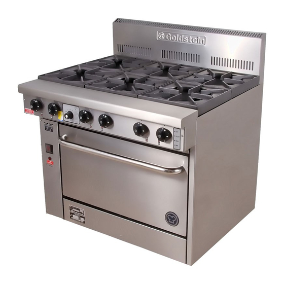
MODELS PF-6-28, PF-12G-4-28, PF-24G-2-28, PF-36-28, PF-4-28
FAN FORCED
WINER OF
AUSTRALIAN
DESIGN COUN
CIL
AWARD 1990
PF-6-28
PF-4-20
GAS APPROVAL 20" No.2494 28" 2498
ESTABLISHED 1911
The Cooking Equipment Professionals
www.goldsteineswood.com.au
Advertisement
Table of Contents

Related Manuals for goldstein PF-6-28

Summary of Contents for goldstein PF-6-28
- Page 1 The Heavyweight 800 Series Performance Plus And Fan Forced Units PROUDLY AUSTRALIAN MADE INSTALLATION PROCEDURE – USER MANUAL SERVICE INSTRUCTION MODELS PF-6-28, PF-12G-4-28, PF-24G-2-28, PF-36-28, PF-4-28 FAN FORCED WINER OF AUSTRALIAN DESIGN COUN AWARD 1990 PF-6-28 PF-4-20 GAS APPROVAL 20” No.2494 28” 2498...
-
Page 2: Table Of Contents
TABLE OF CONTENTS INTRODUCTION Page 3 INSTALLATION Page 4 & 5 COMMISSIONING Page 6 MAINTENANCE Page 7 TRIVETS Page 8 PILOT & BURNER OPERATION Page 9 CONTROL Page 10 THERMOSTAT SETTING Page 11 – 12 - 13 PROBLEM SOLVING Page 14 – 15 - 16 FAN FORCE Page 17 FAN FORCE WIRING DIAGRAM... -
Page 3: Introduction
1. INTRODUCTION Congratulations for purchasing your Goldstein commercial cooking appliance. J. Goldstein & Co. is a wholly owned Australian company and have been operating since 1911, building high quality products. The information in this manual will assist your installer and ensure correct location and connection. -
Page 4: Installation
2. INSTALLATION RECEIVING INSPECTION – PRE-INSTALLATION • Please follow these instructions carefully. • Remove cartons from unit and check for any damages. • Report any damages to the transport company or your dealer. • Lift off base and screw the adjustable legs on the unit, •... - Page 5 2. INSTALLATION INSTALLATION Please follow these instructions carefully All equipment must be sitting level for proper operation and combustion where plinth type installation is made, plinth height and front overhang must be 50 mm minimum. Levelling can be made by the use of metal shims. For performer series where adjustable legs are provided, levelling can be made easily due to the threaded construction of the legs.
-
Page 6: Commissioning
3. COMMISSIONING To be carried out be Gasfitter or Authority service person COMMISSIONING APPLIANCE – DETAILS, TESTING, CHECKING PRESSURE ETC. COMMISSIONING CHECK LIST CHECK FOR DAMAGE AND MISSING PARTS ON BACK OF WARRANTY CARD. REMOVE ALL PLASTIC COATING FROM S/STEEL PANELS. MAKE SURE ALL PARTS ARE IN THEIR CORRECT POSITION E.G. -
Page 7: Maintenance
4. MAINTENANCE MAINTENANCE PROCEDURE USE PROTECTIVE CLOTHING FOR CLEANING TO AVOID DANGEROUS CONTACT WITH HOT SURFACES. CAST IRON TRIVET Wash in WARM soapy water, use Plastic Scourer if necessary. Dry with soft cloth or paper towel. STEEL GRIDDLE PLATES, ALL RANGES & GRIDDLE UNITS Before daily cleaning of the griddle plate, cool the plate to no more than 60 C. -
Page 8: Trivets
5. TRIVETS ENSURE ALL TRIVET ARE PUT ON AS PER DIAGRAM ABOVE, SO THAT THE PILOTS ARE UNDER THE CANOPIES. FAILURE TO PLACE TRIVET CORRECTLY MAY CAUSE A FIRE HAZARD. IM036B2/8... -
Page 9: Pilot & Burner Operation
6. PILOT OPERATION IGNITION POSITION – LIGHT PILOT – (If flame failure hold in for 10 seconds to establish pilot flame). TURN TO FULL ON – MAX GAS FLOW, FURTHER ADJUSTMENT BETWEEN POSITIONS C & D. TURN TO MINIMUM FLOW – MIN. GAS FLOW TO MAINTAIN FLAME (Adjustable to suit type of gas used.) as precise and accurate. -
Page 10: Control
7. CONTROL MODEL EUROSIT 630 OVEN CONTROL IM036B2/10... -
Page 11: Thermostat Setting
7. THERMOSTAT SETTING SETTING The thermostat must be set for an individual appliance at the factory. However, if necessary an authorise person can recalibrate as follows: ♦ Remove knob 1 ♦ Remove nut 2 and 7mm hexagonal spanner ♦ Operate the appliance until an oven temperature of 200°C is reached (or 160°C for a fryer) ♦... - Page 12 8. THERMOSTAT SETTING Cont’d INSTALLATION 630 EUROSIT complies with current safety standards. Nevertheless, its installation on appliances must be verified in accordance with specific standards for each installation. In particular, it is necessary to ensure that requirements relating to the class of flame failure device are met.
- Page 13 8. THERMOSTAT SETTING Cont’d SETTINGS AND ADJUSTMENTS All adjustments must be made on the basis of the specific characteristics of the appliance. Check inlet and outlet pressure using the pressure test points (6 and 7) provided. After testing, carefully seal test points with the provided screws. Recommended Torque: 2.5Nm.
-
Page 14: Problem Solving
9. PROBLEM SOLVING CAUSE AND REMEDY FOR DEFECTIVE OVEN COOKING Too much bottom heat, which results in burning on the bottom of baked products also scorching on the sides. Products will be too light on top, uneven in colour on the top and probably raw in the centre. Cause: Remedy Insufficient (BTU) MJ input. - Page 15 9. PROBLEM SOLVING Cont’d Baking characteristics from front to back. Cause: Remedy Unit not level, front to back Using spirit from front to back, level up appliance by means of adjustable feet. Dried out Product Cause: Remedy Too low a temperature. Adjust thermostat accordingly.
- Page 16 9. PROBLEM SOLVING Cont’d Burner goes out and flashes back Cause Remedy Excessive aeration. Adjust Yellow Flame Cause Remedy Too much gas to burner. Check gas pressure and burner Jet orifice. Cause Remedy Insufficient aeration. Adjust Harsh noisy flame Cause Remedy Excessive aeration Adjust.
-
Page 17: Fan Force
10. FAN FORCE FAN SWITCH NEEDS TO BE ON ALL TIME WHEN OVEN IS USED SPARKER Fan Forced Ovens allow a more even cooking of the product due to the air circulating more freely in the oven and the air movement helps to strip away thin layers of moisture and cool air from around the product allowing the heat to penetrate and reduce cooking time. -
Page 18: Fan Force Wiring Diagram
11. FAN FORCE WIRING DIAGRAM IM036B2/18... -
Page 19: Drawings
12. DRAWING MODEL: PF-24, 32, 36 & MILLENIUM RANGE IM036B2/19... -
Page 20: Spare Parts
13. SPARE PARTS MODEL: PF-24, 32, 36 & MILLENIUM RANGE ITEM No. CODE DESCRIPTION GTR00002 TRIVET – 12” PF RANGE GTC00320 THERMOCOUPLE – L=320 (GRIDDLE) PFG00A02 GREASE CAN ASSY GTR00003 TRIVET – SOLID TOP FOR 12” x 12” (RAW) PFB GBNSP000 SUPPORT BRACKET (GBNBTL00/GBNBTS00) GBNBTL00... - Page 21 13. SPARE PARTS Cont’d MODEL: PF-24, 32, 36 & MILLENIUM RANGE CONT. ITEM No. CODE DESCRIPTION PF-36P24 DRIP TRAY 830mm x 622mm PF-32P24 DRIP TRAY 737mm x 622mm GTC00450 THERMOCOUPLE – L=450 FRONT BURNER GTC00600 THERMOCOUPLE – L=600 REAR BURNER MLESSBFA STAINLESS STEEL LEG WITH ADJ PLASTIC INSERT MLEPLBF1...
-
Page 22: Warranty
(Note: Travel time not covered by warranty). “To the maximum extent permitted by law, any liability on Goldstein/Eswood’s part or on the part of its servants or agents for loss or damage of any kind whatsoever in connection with the products, including liability for or in respect of any claim arising out of contract, negligence or statute, shall not, in any event, exceed $100”... -
Page 23: Branches
15. GOLDSTEIN/ESWOOD BRANCHES For inquiries please call your nearest state branch: Head Office 211-213 Woodpark Road Smithfield NSW 2164 Phone: 02 9604 7333 Fax: 02 9604 5420 Victoria Queensland Unit 13 Nautilus Complex 260-264 Wickham Road Unit 12 Moorabbin 210 Queensport Road...
Need help?
Do you have a question about the PF-6-28 and is the answer not in the manual?
Questions and answers