Advertisement
Table of Contents
- 1 Table of Contents
- 2 Safety Instructions
- 3 Conditions of Use
- 4 Presentation and Features
- 5 Installation Instructions
- 6 Installation Method Using Truss Hooks
- 7 Dmx512 Connection
- 8 Master/Slave Mode Settings
- 9 DMX Chart
- 10 Error Messages
- 11 Care and Maintenance
- 12 Technical Specifications
- Download this manual
Advertisement
Table of Contents

Related Manuals for Ayrton MagicBlade R


Summary of Contents for Ayrton MagicBlade R
- Page 1 USER MANUAL V.1 ENGLISH VERSION 01 05 2015...
-
Page 3: Table Of Contents
Description Installation instructions Installation method using truss hooks DMX512 connection Instructions for using the wireless internal DMX system Control Panel MagicBlade R control panel menu - Option details Master/Slave Mode settings Led mapping DMX Chart Error Messages Care and maintenance... -
Page 4: Safety Instructions
All the information found in this manual Be careful to power off your MAGICBLADE-R by removing the power plug is subject to change without notice. AYRTON reserves the right to modify from the source, before connecting or disconnecting the luminaire. -
Page 5: Presentation And Features
Remote Device Management cause breakage of the plastic parts or the body. AYRTON cannot be held (RDM)-type DMX controller may be required. The DMX RDM protocol is a responsible for the luminaire’s broken plastic parts or body, which are not... -
Page 6: Installation Instructions
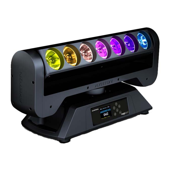
dEScrIPtIon The MAGICBLADE-R consists of a metal frame and plastic covers. The power connectors and DMX512 signal connectors are on the back of the fixture’s base. dImEnSIonS Bottom view Front view 1. Collimator 2. LCD Display 3. Left button 4. MODE/ESC button 5. -
Page 7: Dmx512 Connection
The installation must always be secured at a second attach point, e.g., by • Attach the clamp to the omega bracket using an M12 screw. a safety cable of the appropriate size. • Insert the quick-lock fasteners of the first omega bracket into the Do not stand under the luminaire while it is being installed, dismantled respective holes on the base of the unit. - Page 8 InStructIonS uSInG WIrELESS DMX512 CONNECTION WITH TERMINATION PLUG IntErnAL dmX SYStEm For installations where the DMX cable must extend over long distances, or if it is located near areas with major electrical disturbance, it is 1. REQUIRED HARDWARE recommended to use a DMX termination plug. This helps prevent luminaires from malfunctioning due to interference.
- Page 9 • Do not connect the DMX console to the fixture when it is controlled Address Set Dmx Addr A001~AXXX DMX address setting via wireless. This could cause interference between the two modes of User Mode Stand Mode User’s mode to change Basic Mode channel numbers operation.
- Page 10 mAGIcBLAdE-r controL PAnEL mEnu – oPtIon Tilt Reverse Reverses the direction of the TILT movement. dEtAILS w Access the menu by pressing the “Mode Esc” key. w Use the up/down arrow keys to reach the “OPTION” menu and press The following section provides details on the options that can be selected “Enter.”...
- Page 11 SERVICE PIN FAN CONTROL Head Control Allows you to choose the fan speed on the fixture head. The options are WARNING! For normal operation the “Service pin” menu information AUTO, HIGH or LOW. should not be changed. Contact your dealer for more information. w Access the menu by pressing the “Mode Esc”...
- Page 12 LED CONTROL Set To Slave Defines whether the Kling-Net Protocol is used to control the LEDs. Kling- Sets the fixture to SLAVE Mode for receiving instructions from a master Net is a protocol designed by Arkaos ™ that simplifies use of their media luminaire (see Master/Save mode settings, below).
-
Page 13: Master/Slave Mode Settings
Timer PIN TEST CHANNEL The “Timer PIN” is the password required to reset the counter for “Last Tests each of the fixture’s settings (e.g., PAN, TILT). Run Hrs.” The PWD is 038. w Access the menu by pressing the “Mode Esc” key. w Access the menu by pressing the “Mode Esc”... - Page 14 was assigned to “Slave 2”, the SLAVE fixture would receive the program The 3 groups of SLAVE fixtures run the “Auto Program” function in the “Auto Program Part 2” from the MASTER fixture. following sequence: To launch a program, follow this procedure: Part 1: 1.
-
Page 15: Dmx Chart
dmX cHArt DMX channel´s functions and their values (44 DMX channels) DMX channel´s functions and their values (44 DMX channels) Mode/Channel Value Function Mode/Channel Value Function Shutter, strobe: PAN Movement 8bit 0-31 Led turn off 0-255 Pan Movement 32-63 Led turn on Pan Fine 16bit 64-95 Strobe effect slow to fast... -
Page 16: Error Messages
Internal program 5 (secne33~40 of EEPROM) 200-219 Internal program 6 (secne41~48 of EEPROM) Ayrton is continually upgrading this product line. It is therefore possible 220-239 Internal program 7 (secne49~56 of EEPROM) that a new software version is available that will increase the unit’s... -
Page 17: Technical Specifications
POWER Never use alcohol or any chemical agent to clean the optical system • Electronic power distribution with Power Factor Correction (PFC) from of an Ayrton product. 110-240 VAC, 50/60 Hz • 200 Watt maximum power • Power supply via powerCON TRUE1 connector COMPLIANCE CHECk •... - Page 18 In addition, cosmetic defects caused by the normal wear and tear of the unit are not covered under the warranty. Any modification to the fixture will void the warranty. AYRTON cannot under any circumstances be held liable for quality and conformity regarding the installation of this product, which is the responsibility of the installer.
- Page 19 USER MANUAL _ 19...
- Page 20 www.ayrton.eu...
Need help?
Do you have a question about the MagicBlade R and is the answer not in the manual?
Questions and answers