Table of Contents
Advertisement
SERVICE
MICROWAVE OVEN
MICROWAVE OVEN
MD800WC (WHITE)
MD800SC (SILVER)
Manual
CONTENTS
1. Precaution .......................................... 1
2. Specifications .................................... 3
3. Operating Instructions....................... 4
4. Disassembly and Reassembly ....... 5
5. Alignment and Adjustment ............. 9
6. Troubleshooting ............................... 13
7. Exploded Views and Parts List .... 15
8. PCB Diagrams ................................. 19
9. Schematic Diagrams ....................... 21
SAM0013
Advertisement
Table of Contents

Subscribe to Our Youtube Channel
Related Manuals for Samsung MD800WC


Summary of Contents for Samsung MD800WC
-
Page 1: Table Of Contents
MICROWAVE OVEN MD800WC (WHITE) MD800SC (SILVER) SERVICE Manual MICROWAVE OVEN CONTENTS 1. Precaution .......... 1 2. Specifications ........3 3. Operating Instructions....... 4 4. Disassembly and Reassembly ..5 5. Alignment and Adjustment ..... 9 6. Troubleshooting ....... 13 7. Exploded Views and Parts List ..15 8. -
Page 2: Exposure To Excessive Microwave Energy
PRECAUTIONS TO BE OBSERVED BEFORE AND DURING SERVICING TO AVOID POSSIBLE EXPOSURE TO EXCESSIVE MICROWAVE ENERGY (a) Do not operate or allow the oven to be (c) Before turning on microwave power operated with the door open. for any service test or inspection within (b) Make the following safety checks on the microwave generating all ovens to be serviced before activating... -
Page 3: Precaution
1. Precaution Follow these special safety precautions. Although the microwave oven is completely safe during ordinary use, repair work can be extremely hazardous due to possible exposure to microwave radiation, as well as potentially lethal high voltages and currents. 1-1 Safety precautions ( 1. -
Page 4: Special High Voltage Precautions
1-2 Special Servicing Precautions (Continued) 17. When checking the continuity of the switches or transformer, always make sure that the power is OFF, and one of the lead wires is disconnected. 18. Components that are critical for safety are indicated in the circuit diagram by shading, 19. -
Page 5: Specifications
2. Specifications 2-1 Table of Specifications TIMER 99 MINUTES 99SECONDS POWER SOURCE 120V 60Hz, AC POWER CONSUMPTION MICROWAVE : 1,150W OUTPUT POWER FROM 80 TO 800W ( 10 LEVEL POWER ) (ICE-705 TEST PROCEDURE) OPERATING FREQUENCY 2,450MHz MAGNETRON OM75S(20) COOLING METHOD COOLING FAN MOTOR OUTSIDE DIMENSIONS 16"(W) x 12... -
Page 6: Operating Instructions
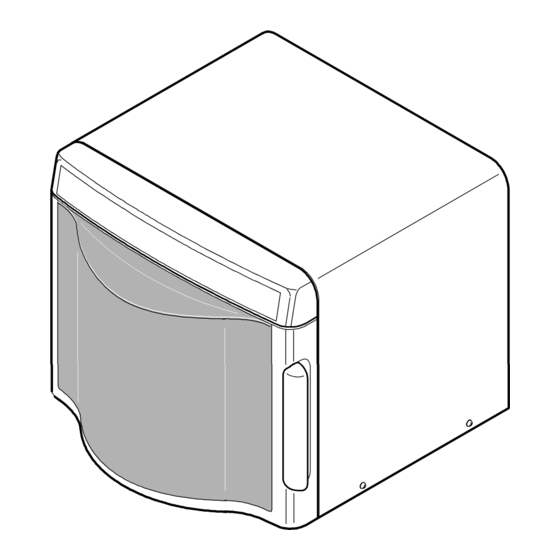
3. Operating Instructions 3-1 Control Panel 3-2 Features & External Views 215 mm 305 mm 406.5 mm 437 mm - 4 -... -
Page 7: Disassembly And Reassembly
4. Disassembly and Reassembly 4-1 Replacement of Magnetron, Motor Assembly and Lamp Remove the magnetron including the shield case, permanent magnet, choke coils and capacitors (all of which are contained in one assembly). 1. Disconnect all lead wires from the magnetron. 2. -
Page 8: Replacement Of Control Circuit Board
4-3 Replacement of Control Circuit Board 4-3-1 Removal of Control Box Assembly SCREW 1. Remove the screws securing the out panel and take out the out panel. 2. Disconnect all lead wires from the control box. SCREW 3. Remove screws securing the rear of the control box. Control-box 4. -
Page 9: Replacement Of Fuse
4-4 Replacement of Fuse 1. Disconnect the oven from the power source. 2. When 15A fuse blows out by the operation of interlock monitor switch failure, replace the primary interlock switch, door sensing switch, monitor switch and power relay. 3. When the above three switches operate properly, check if any other part such as the control circuit board, blower motor or high voltage transformer is defective. -
Page 10: Reassembly Test
4-6-2 Removal of Door "E " 1. Following the procedure as shown in the figure, Door "E" insert and bend a thin metal plate between Door "E" and Door "A" until you hear the 'tick' sound. 2. Insertion depth of the thin metal plate should be 0.5mm or less. -
Page 11: Alignment And Adjustment
5. Alignment and Adjustments PRECAUTION 1. High voltage is present at the high voltage terminals during any cook cycle. 2. It is neither necessary nor advisable to attempt measurement of the high voltage. 3. Before touching any oven components or wiring, always unplug the oven from its power source and discharge the high voltage capacitor. -
Page 12: High Voltage Capacitor
5-4 High Voltage Capacitor 1. Check continuity of the capacitor with the meter set at the highest resistance scale. 2. Once the capacitor is charged, a normal capacitor shows continuity for a short time, and then indicates 9M Ω . 3. -
Page 13: Output Power Of Magnetron
5-8 Output Power of Magnetron CAUTION MICROWAVE RADIATION PERSONNEL SHOULD NOT ALLOW EXPOSURE TO MICROWAVE RADIATION FROM MICROWAVE GENERATOR OR OTHER PARTS CONDUCTING MICROWAVE ENERGY. The output power of the magnetron can be measured by performing a water temperature rise test. Equipment needed : * Two 1-liter cylindrical borosilicate glass vessel (Outside diameter 190 mm) * One glass thermometer with mercury column... -
Page 14: Procedure For Measurement Of Microwave Energy Leakage
5-10 Procedure for Measurement of Microwave Energy Leakage 1. Pour 275±15cc of 20±5°C(68±9°F) water in a beaker which is graduated to 600cc, and place the beaker in the center of the oven. 2. Start to operate the oven and measure the leakage by using a microwave energy survey meter. -
Page 15: Troubleshooting
6. Troubleshooting PRECAUTION 1. CHECK GROUNDING BEFORE CHECKING FOR TROUBLE. 2. BE CAREFUL OF THE HIGH VOLTAGE CIRCUIT. 3. DISCHARGE THE HIGH VOLTAGE CAPACITOR. 4. WHEN CHECKING THE CONTINUITY OF THE SWITCHES OR TRANSFORMER, DISCONNECT ONE LEAD WIRE FROM THESE PARTS AND THEN CHECK CONTINUITY WITHOUT THE POWER SOURCE ON. - Page 16 6-1 Electrical Malfunction(continued) SYMPTOM CAUSE CORRECTIONS Oven lamp and fan motor turn on 1. Misadjustment or loose wiring Adjust door and latch switches. of secondary latch switch 2. Defective Secondary latch switch Oven can program but timer 1. Open or loose wiring of Adjust door and interlock does not start.
-
Page 17: Exploded Views And Parts List
7. Exploded Views and Parts List 7-1 Exploded Views M162 M001 C117 C003 C127 T001 C080 T017 M029 C081 M030 M039 P165 M020 M023 H018 M040 M041 M022 C082 M035 P096 M015 C004 M019 M037 M034 M049 C084 M018 M036 C005 D049 B006... -
Page 18: Main Parts List
ASSY BODY LATCH MW8ROWC,ROUND-MWO,0.8CUF C003 RAS-K2LED-01 ASSY PCB PART MD800,120V60HZ C080 DE61-00522A BRACKET-PCB MW8ROWC,PP,-,-,-,-,ROUND-MWO C081 DE66-20095B BUTTON-LOCK -,-,OTR5,-,-TB53 C117 DE97-00436A ASSY-BRACKET PCB MD800WC/XAA,-,-,- C127 DE62-00047A INSULATION-PAPER MD800WC/SC,PAPER,TO.23 BKT-PCB H018 DE31-90054A BLADE-FAN PP,-,100MM,JE320WA,GA,-,-,- M001 DE64-00889A PANEL-OUTER MW8ROWC,SECC,T0.5+0.2,W406.5 White M001 DE64-00889B PANEL-OUTER MR87/MR89,CABS(HR0370),T2.5+0.2... - Page 19 7-3 Control and Door Parts List Code No. Description Specification Q'ty Remark C004 DE34-00194A SWITCH MEMBRANE MD800WC,SEA,-,-,-,120V/6 White C004 DE34-00194B SWITCH MEMBRANE MD800SC,SEA,-,-,-,120V/6 Silver C005 DE64-00894A CONTROL-PANEL(TC) MW8ROWC,ABS(VH0800),T2 White C005 DE64-00894B CONTROL-PANEL(TC) MD800SC,ABS,-,-,-,-,VICTORY-SIL Silver C009 DE64-00897A WINDOW-DISPLAY(TC) MW8ROWC,SAN(S1906),T2 C082 DE94-00857A...
-
Page 20: Standard Parts List
7-4 Standard Parts List Code No. Description Specification Q'ty Remark DE60-30015A NUT-FLANGE M5,P0.8,MSWR10,FEFZY,-,-,-,-,- 6006-001170 SCREW-ASSY TAPP WS,TH,+,M4,L10,ZPC(YEL) BASE-PLATE 6006-001170 SCREW-ASSY TAPP WS,TH,+,M4,L10,ZPC(YEL) PCB-GRO 6006-001170 SCREW-ASSY TAPP WS,TH,+,M4,L10,ZPC(YEL) POW-GRO 6006-001174 SCREW-ASSY TAPP WE,TH,+,M4,L12,ZPC(YEL) BKT-HVC + C/BACK 6006-001176 SCREW-ASSY TAPT WT,PH,+,M4,L8,ZPC(YEL) 6002-000231 SCREW-TAPPING TH,+,2S,M4,L12,ZPC(YEL),SM20C BACK-CAVI... -
Page 21: Pcb Diagrams
8. P.C.B Diagrams 8-1 P.C.B Diagrams ( This Document can not be used without Samsung's authorization ) - 19 -... - Page 22 8-2 P.C.B Parts List Code No. Description Specification Q'ty Remark 3501-001155 RELAY-MINIATURE 24VDC,200MW,3000MA,1FORMA,10MS,10MS RY01,RY03 3501-001188 RELAY-POWER 24V DC,0.53W,-,1FORMA,9.3MS,10MS RY02 3708-000528 CONNECTOR-FPC/FFC/PIC 13P,2.54mm,STRAIGHT,SN DSP1 3708-001553 CONNECTOR-FPC/FFC/PIC 10P,1.25mm,STRAIGHT,SN CN01 DE09-00051A IC MICOM S3P7054DZZ-SOT4,OTP,SOP,4BIT-32PIN,-,-,-,-,-,-,- IC01 DE26-00037A TRANS L.V SLV-4290U,120V,60Hz,AC17V/7V,-,35*10,PIN,- LVT1 DE30-20016A BUZZER CBE2220BA,STICK,-,-,-,-,-,-,- BZ01 DE92-01413A ASSY PCB AUTO-MAIN...
-
Page 23: Schematic Diagrams
9. Schematic Diagrams 9-1 Schematic Diagrams ( This Document can not be used without Samsung's authorization ) MAGNETRON BLK BLU HIGH VOLTAGE DIODE TO CHASSIS PRIMARY SWITCH HIGH VOLTAGE CAPACITOR RED BLU DOOR SENSING SWITCH MONITOR SWITCH BOTTOM CENTER SYMBOL... - Page 24 ELECTRONICS ©Samsung Electronics Co., Ltd. May 2003 This Service Manual is a property of Samsung Electronics Co.,Ltd. Printed in Korea Any unauthorized use of Manual can be punished under applicable International and/or domestic law Code No. : DE68-03161A...
Need help?
Do you have a question about the MD800WC and is the answer not in the manual?
Questions and answers