Table of Contents
Advertisement
Quick Links
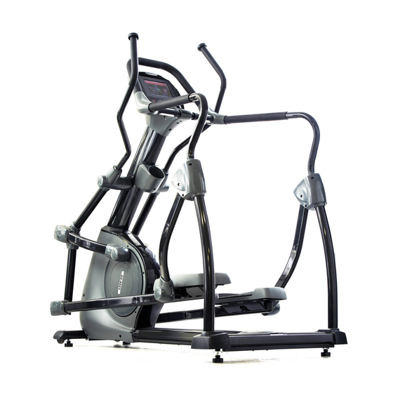
OWNER'S MANUAL
PR-8623
CAUTION:
Weight on this product should not exceed 181 kgs/ 400 lbs
CLIMBER
WARNING
Exercise can present a health
risk. Consult a physician before
beginning any exercise program
with this equipment.
If you feel faint or dizzy,
immediately discontinue use of
this equipment. Serious bodily
injury can occur if this
equipment is not assembled
and used correctly. Serious
bodily injury can also occur if all
instructions are not followed.
Keep children and pets away
from equipment when in use.
Always make sure all bolts and
nuts are tightened prior to each
use. Follow all safety
instructions in this manual.
Product May Vary Slightly From Picture.
MADE IN TAIWAN
v.II
Advertisement
Table of Contents

Related Manuals for STI CLIMBER PR-8623

Summary of Contents for STI CLIMBER PR-8623
- Page 1 OWNER’S MANUAL CLIMBER PR-8623 WARNING Exercise can present a health risk. Consult a physician before beginning any exercise program with this equipment. If you feel faint or dizzy, immediately discontinue use of this equipment. Serious bodily injury can occur if this equipment is not assembled and used correctly.
-
Page 2: Safety Instructions
SAFETY INSTRUCTIONS WARNING: To reduce the risk of serious injury, read the following Safety Instructions before using the Climber. 1. Read all warnings posted on the Climber. 2. Read this Owner's Manual and follow it carefully before using the Climber. Make sure that it is properly assembled and tightened before use. - Page 3 “B EFORE EGIN” /Thank you for choosing the Climber. We take great Too often, our busy lifestyles limit our time and pride in producing this quality product and hope it will opportunity to exercise. The Climber provides a provide many hours of quality exercise to make you convenient and simple method to begin your assault feel better, look better and enjoy life to its fullest.
- Page 4 “H ARDWARE DENTIFICATION HART” Unpack the box in a clear area. Use the List of Hardware below to check the contents of the hardware kit. This chart is provided to help identify the hardware used in the assembly process. Place the washers, the end of bolts, or screws on the circles to check for the correct diameter.
- Page 5 Q’TY Part No. and Description HARDWARE KIT Self-Tapping Screw, Flat Head (M4x20mm) 125 Bolt, Round Head (M5xp0.8x15mm) 134 Bolt, Socket Head (M8xp1.25x10mm) 146 Bolt, Socket Head (M10xp1.5x110mm) 154 Nylon Nut (M10xp1.5)
- Page 6 Unpack the box in a clear area. Follow the List of Assembly Parts below to check “A and make sure all assembly parts are present and in good condition. Do not dispose SSEMBLY ARTS” of the packing material until the assembly process is completed. Assembly tools and hardware kit have included for you to use when assembling the product Rotator Cuff –...
-
Page 7: Step 1 - Leveler Assembly
“A SSEMBLY NSTRUCTIONS” Place all parts from the box in a cleared area and position them on the floor in front of you. Remove all packing materials from your area and place them back into the box. Do not dispose of the packing materials until assembly is completed. Read each step carefully before beginning. - Page 8 Attach the Front Stabilizer (2) onto the Main Frame (1) and secure with 2pcs Washers (8x38x2.0t)(114), 2pcs Lock Washers (M8)(111) and 2pcs Bolts, Hex Head (M8xp1.25x65mm)(141). b. NOTE: 4pcs Bolt, Socket Head (M8×p1.25×65mm)(137) and Nylon Nut (M8xp1.25)(152) are attached on the front of the Rear Stabilizer (3), and 2pcs Bolts, Round Head (M5×p0.8×15mm)(125) are attached on the rear of the Main Frame (1) as the left draft shown.
- Page 9 – TEP 4 Upright Post Assembly a. 2pcs Thin Nylock Nuts (M10xp1.5)(153) have preassembled into the front of the Main Frame (1) as the following drawing shows (they will not be tight, so that slotted bracket of the upright post will slide between the nut and the frame).
- Page 10 Arm Linkage (16). b. Following the drawing’s line to attach the front of the Pivoting Arm Linkage (16) to the Right Pivoting Arm (15A) and the rear of the Pivoting Arm Linkage (16) to the Crank Cover by each secure with 1pcs Bolt, Hex Head (M10×p1.5×70mm)(145), 1pcs Nylon Nut (M10xp1.5)(154).
- Page 11 “A SSEMBLY NSTRUCTIONS” – TEP 7 Wire & U-Shaped Handlebar Stand Assembly NOTE: For shipping purpose, 4pcs Lock Washers (M8)(111) and 4pcs Bolts, Button Head (M8×p1.25×16mm)(130) are attached to U-Shaped Handlebar Stand (9) as the following draft shown. a. Remove 4pcs Lock Washers (M8)(111) and 4pcs Bolts, Button Head (M8×p1.25×16mm)(130)
- Page 12 “A SSEMBLY NSTRUCTIONS” – TEP 9 Bottom Handrail Decoration Cover Assembly a. Follow the above drawing to first attach the Left Bottom Handrail Decoration Cover - Inner (7) onto the inner side of the Rear Stabilizer (3). NOTE: Please make sure Inner Decoration Cover (7)’s two ribs insert into the two holes located on...
- Page 13 “A SSEMBLY NSTRUCTIONS” 11 – Pedal Support Arm Assembly NOTE: For shipping purpose, 4pcs Bolts, Round Head (M5xp0.8x15mm)(125), 1pcs Bolt, Hex Head M10×p1.5×70mm) (145) and 1pcs Nylon Nut (M10xp1.5)(154) are attached to the front of the Right Pedal Support Arm (18).
-
Page 14: Console Assembly
4pcs Bolts, Round Head (M5xp0.8x15mm)(125). Repeat the above same procedure for the left side. “A SSEMBLY NSTRUCTIONS” – TEP 14 Wire and Console Assembly a. Connect the Upper Connection Wire (157) to the Middle Connection Wire (158). NOTE: Be careful not to pinch the wires. b. - Page 15 “A SSEMBLY NSTRUCTIONS” – TEP 18 U-Shaped Handlebar Assembly NOTE: For shipping purpose, 4pcs Bolts, Button Head (M8×p1.25×50mm)(131) and 4pcs Nylon Nuts (M8xp1.25)(152) are attached to U-Shaped Handlebar (8) as the draft shown on the right. a. Remove 4pcs Bolts, Button Head (M8×p1.25×50mm)(131) and 4pcs Nylon Nuts (M8xp1.25)(152) from the U-Shaped Handlebar (8).
- Page 16 “A SSEMBLY NSTRUCTIONS” – TEP 20 Upper Handlebar & Rotator Cuff–Pivoting Arm Assembly NOTE: 4pcs Bolts, Hex Head Flange (M8×p1.25×16mm)(177) are attached to on the rear of Right Upper Handlebar (13) as the draft shown on the right. a. Remove 4pcs Bolts, Hex Head Flange (M8xp1.25x16mm)(177) from the rear of Right Upper Handlebar (13).
-
Page 17: How To Tow The Item Safely
**For the final step, make sure all the bolts and nuts are fully tightened before using the item** “O PERATIONAL NSTRUCTIONS” OW TO ADJUST CONSOLE ANGLE To get the best console angle, it’s suggested to use both hands to hold the upper and lower end of the console (area A or B) and gently adjust the console angle to the proper position. -
Page 18: Function Description
“C ONSOLE VERVIEW & ONSOLE UTTON” Speaker Speaker Press H.R. Trend to review your heart rate chart during exercise. For program profiles (such as Mountain, Random program, except for Manual & Constant Power program, the “LEVEL” here means “Workout Difficulty Level”. MP3/CD player Jack Headphone... - Page 19 BACK Press BACK to return to previous page “C NSTRUCTIONS – ONSOLE ONSOLE UTTON” onsole uttons: H.R. Trend: Press H.R. Trend to review your heart rate chart. The Heart Rate Trend is recorded automatically in every 60 seconds if the user’s actual heart rate is able to detect by the console.
- Page 20 WATT: Display range: 0 ~ 999 Watt. “C NSTRUCTIONS – ONSOLE ONSOLE UNCTION” LEVEL: For this TFT console, the LEVEL HAS TWO MEANINGS, SINCERELY PLEASE TAKE A LOOK BELOW, For Manual, Constant Power Program, Level means “resistance/tension level”; Display range: 1 ~ 20 resistance levels.
-
Page 21: Power Off
The harder your body works during the activity, the more oxygen is consumed and the higher the MET level. If you are exercising at a level of 7 METS, this means that you are working about 7 times as hard as you would be at rest. You are consuming about 7 times the amount of oxygen as you would at rest as well. -
Page 22: Console Operation
2. Profile: including Basic profile and Advanced profile. 3. Heart Rate Control (60%, 65%, 70%, 75%, 80% and 85%) “C PERATION – ONSOLE UICK TART” uick tart: 1. Press “Quick Start” on Boot Screen. After selecting Quick Start, following countdown pages will display sequentially. ►The countdown pages will appear before every entry of final main page. - Page 23 PAUSE Press to pause all functions during Press START to start workout your exercise program. All the data on the display will pause except for PULSE readout “C PERATION – ONSOLE ROFILE” rofile: 1. Press “Profile” on Boot Screen. 2. Enter into Main Profile Selecting page. Main Profile Selecting There are 2 workout profiles for options.
- Page 24 “C PERATION – ONSOLE ASIC ROFILE” “A” Basic Profile Instruction: 1. Press “Basic Profile”. 2. Enter into diagrams’ selection page. Options include Manual, Fitness, Random, Rolling, Fat Burn, Ascent, total in 6 diagrams. Press the desired diagram to workout. NOTE: When enter into Random profile, the workout profile will randomly create each...
- Page 25 NOTE: Display range from 30~181kgs Press QUICK START to Press BACK to return to start exercise immediately. previous page. Press NEXT to enter into TIME Page for setting the desired time. “C PERATION – ONSOLE ASIC ROFILE” 4. Enter into Time page and select the desired value of time; display range: 5:00 ~ 99:00. NOTE: Display range from 5:00 ~ 99:00 Press QUICK START to...
- Page 26 STATISTICS: Press STATISTICS to review your average value of workout statistics. NOTE: The button is able to press at anytime to review during exercise. Press Back to return to the workout program. “C PERATION – ONSOLE DVANCED ROFILE” “A” Advanced Profile Instruction: 1.
- Page 27 Before operating CONSTANT POWER PROGRAM, review the difference between the CONSTANT POWER and the CONSTANT RESISTANCE function: Level Control (Constant Resistance) in most of workout Watt Control (Constant Power) in Constant Power program programs The resistance depends on the value of RPM (Rotate Per Minute.) “RPM...
- Page 28 “B” Instruction Note for During Exercise: H.R. Trend: Press H.R. Trend to review your heart rate chart. The Heart Rate Trend is recorded automatically in every 60 seconds if the user’s actual heart rate is able to be detected by the console. NOTE: Please be sure to wear a chest belt or place both of hands on the Pulse Sensors located on the Handlebar in order to make sure...
-
Page 29: Operation
2. Enter into Weight page and input the value of weight; display range: 30 ~ 181 kgs. NOTE: Display range from 30~181kgs Press QUICK START to Press BACK to return to start exercise immediately. previous page. Press NEXT to enter into TIME Page for setting the desired time. - Page 30 5. Enter into Gender page and select your gender. Press QUICK START to Press BACK to return start exercise immediately. to previous page. Press NEXT to select target heart rate. “C PERATION – ONSOLE EART ONTROL ROFILE” 6. Select your ideal target heart rate (60%, 65%, 70%, 75%, 80% and 85%). NOTE for H.R.C.
- Page 31 that the pulse readout could be able to detect. Press H.R. Trend again to return to the workout program. STATISTICS: Press STATISTICS to review your average value of workout statistics. NOTE: The button is able to press at anytime to review during exercise. Press Back to return to the workout program.
- Page 32 During the first few months of your exercise Target Heart Rate Zone Average Max. Heart program, keep your heart rate near the low end (55% ~ 90% of Max. Rate 100% of your target zone as you exercise. After a few Heart Rate) months, your heart rate can be increased 110-180 beats per minute...
- Page 33 leg. Bent Torso Pulls Bent Over Leg Stretch While sitting on the floor, Stand with feet shoulder-width have legs apart one leg apart and lean forward as straight and one knee bent. illustrated. Using the arms, Pull the chest down to touch gently pull the upper body the thigh on the leg that is towards the right leg.
- Page 34 Inner Rotator Cuff-Pivoting Arm Foam Grip for Dual-Action Handlebar Pivot Ring Front Rotator Cuff- Pivoting Arm Console Rear Rotator Cuff- Pivoting Arm Console Lower Case Left Pivot Cuff- Inner Console Bracket Left Pivot Cuff- Outer Upper Handlebar Decoration Cover Right Pivot Cuff- Inner Lower Handlebar Decoration Cover Right Pivot Cuff- Outer Foam Grip-Stationary Handlebar...
- Page 35 118 Screw (M4×12mm) 137 Bolt (M8×p1.25×65mm) 119 Screw (M3×10mm) 138 Bolt (M10×p1.5×70mm) 120 Screw (M3×25mm) 139 Bolt (M8×p1.25×15mm) 121 Screw (M4×20mm) 140 Bolt (M8×p1.25×15mm) 122 Screw (M5×18mm) 141 Bolt (M8×p1.25×65mm) 123 Bolt (M8×1.25×10mm) 142 Bolt (M8×p1.25×80mm) 124 Bolt (M5×p0.8×6mm) 143 Bolt (M10×p1.5×50mm) 125 Bolt (M5×p0.8×15mm) 144 Bolt (M10×p1.5×60mm) 126 Bolt (M5×p0.8×30mm)
- Page 36 177 Bolt (M8×p1.25×16mm) 182 Square Plug PRODUCT PARTS DRAWING (A)
-
Page 37: Product Parts Drawing (B)
PRODUCT PARTS DRAWING (B)
Need help?
Do you have a question about the CLIMBER PR-8623 and is the answer not in the manual?
Questions and answers