Table of Contents
Advertisement
Advertisement
Table of Contents

Related Manuals for Gree GWH09NA-K3NNB1C


Summary of Contents for Gree GWH09NA-K3NNB1C
-
Page 1: Service Manual
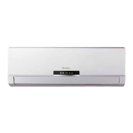
Change for Life Service Manual... - Page 4 T-ON T-OFF AUTO SWING COOL SLEEP LOCK SPEED HEAT ON/OFF MODE SWING SLEEP TIMER...
- Page 5 Installing, starting up, and servicing air conditioner can be Make sure the outdoor unit is installed on a stable, level hazardous due to system pressure, electrical components, surface with no accumulation of snow, leaves, or trash and equipment location, etc. beside.
-
Page 10: Outdoor Temp.
Cooling Heating Condition Condition Indoor:DB27℃ WB19℃ Indoor:DB20℃ Indoor air flow: Super High Indoor air flow: Pipe length:5m Super High Pipe length:5m 32 33 34 35 36 37 38 39 40 41 42 43 44 45 -15 -13-11 -9 -7 -5 -3 -1 1 3 5 7 9 11 Outdoor temp.( ) Outdoor temp.( ) - Page 11 Model...
-
Page 12: Indoor Unit
Outdoor unit Indoor unit Wide tube service Accumlator valve Wide tube 4-way valve Narrow tube service Capillary tube valve Narrow tube Strainer Capillary tube Cooling cycle Heating cycle... - Page 13 Symbol Color symbol ORANGE POWER DISPLAY BN(BK) VIOLET PIPE ROOM BU(WH) TEM.SENSOR TEM.SENSOR WHITE YEGN(GN) YELLOW W1BU CONN WIRE YEGN YELLOW GREEN W2BK OVERLOAD TUBE ROOM W4VT DISP1 DISP2 BROWN W5OG BLUE AC-L COMP BLACK YEGN YEGN PRINTED CIRCUIT BOARD Symbol Parts name JUMP...
- Page 14 COMPRESSOR C(T,U) YEGN COMP S(W,X) R(M,V) FAN MOTOR BU(BK) YEGN YEGN N(1) TERMINAL BLOCK...
-
Page 15: Top View
TOP VIEW Compressor control relay K1 Protective tube PG motor control terminal 4-way valve control terminal & control relay K115 Outdoor fan control terminal & control relay K114 Auto button Up & down swing control terminal PG motor feedback terminal Display control terminal Tube temperature sensor connector... - Page 16 TOP VIEW Compressor control relay Protective tube Indoor fan controls terminal Terminal of power neutral wire interface 4-way valve control terminal and relay K115 Outdoor fan control terminal and relay K114 Auto button Up&down swing control terminal Interface feedback from indoor fan Display control terminal Interface of pipe temperature sensor Interface of ambient temperature sensor...
- Page 17 ON/OFF Press it to start or stop operation. MODE Press it to select operation mode(AUTO/COOL/DRY/FAN/HEAT). : Press it to decrease temperature setting. : Press it to increase temperature setting. Press it to set fan speed. SWING Press it set swing angle. SLEEP TIMER Press it set auto-on/auto-off timer.
-
Page 18: Replacement Of Batteries
SLEEP: Press this button to go into the SLEEP operation mode. Press it again to cancel. This function is available in COOL , HEAT (Only for models with heating function) or DRY mode to maintain the most comfortable temperature for you. TIMER: Press this button to initiate auto-on/auto-off timer. -
Page 19: Temperature Parameters
1 Temperature Parameters Indoor preset temperature (Tpreset) Indoor ambient temperature (Tamb.) 2 Basic functions ( The temperature in this manual is expressed by Centigrade. If Fahrenheit , is used, the switchover between them is Tf=TcX1.8+32.) Once the unit is energized, the compressor shall never be restarted except 3mins interval at least. For the first energization, if the unit is at off status before power failure, the compressor can be restarted without 3-min delay. -
Page 20: Heating Mode
(2)Dry Mode Dry Conditions and Process When Tamb. Tpreset+2 , the unit will run in dry and cooling mode, in that case the compressor and outdoor fan will run and the indoor fan will run at low speed. When Tpreset-2 Tamb. - Page 21 Defrosting Conditions and Process The unit with intelligent defrosting function can defrost according to frosting conditions. Dual8 displays H1. Protection Function High Temp Resistance Protection If it is detected that the evaporator tube temperature is superheating, the outdoor fan will stop working. When the tube temperature resumes to normal condition, the outdoor fan will resume running.
-
Page 22: Power-Off Memory
(6)Dry Function This function can be set in cooling or dry mode. (7)Automatic Control of Fan Speed In this mode, the indoor fan will automatically select high, medium or low speed with the change of ambient temperature. (8)Up & Down Swing After energization, up &... - Page 25 Space to the ceiling 15cm Above Space to the wall 15cm Above 15cm Above Space to the wall 300cm Above Above Air outlet side Space to the floor The dimensions of the space necessary for proper installation of the unit includ e the minimum permissible distances to adjacent parts .
- Page 26 Wall Wall Wall Wall Mark on the middle of it Gradienter Mark on the middle of it Gradienter Space Space Space Space to the to the to the to the wall wall wall wall above above above above Right Right Left Left Ф55...
- Page 27 Wiring Cover yellow- blue black violet orange Fig 2 green outdoor unit connection External connection Gas side piping electric wire Liquid side piping Tailing 2 Tailing 1 Gas side piping Liquid side insulation Piping insulation Fig.3 Finally wrap it Water drainage pipe with tape Left Left rear...
- Page 28 Handle N(1) 2 yellow- blue black violet orange green Manifold Valve Multimeter Manometer -76cmHg Hi handle Lo Handle Charging hose Low pressure valve Vacuum pump Fig.5 Drain-water hole Bottom frame Drain connecter Hose (available commercially, inner dia. 16mm)
-
Page 29: Items To Be Checked
Items to be checked Possible malfunction Has the unit been fixed firmly? The unit may drop, shake or emit noise. It may cause insufficient cooling(heating) Have you done the refrigerant leakage test? It may cause condensation. Is thermal insulation sufficient? Is water drainage satisfactory? It may cause water leakage. - Page 30 Fig. a Fig. b Air filter Healthy filter Fig.
- Page 47 Start Is the wiring terminal between temperature sensor and the controller loosened or poor ly contacted? Insert the temperature sensor tightly Malfunction is eliminated. Is there short circuit due to trip over of the par ts? Make the parts upright Malfunction is eliminated.
- Page 48 Possible causes: 1. Fan motor is locked; 2. The feedback terminal of PG motor is not connected tightly; 3. The control terminal of PG motor is not connected tightly; 4. Motor is damaged; 5. Malfunction of the rotation speed detection circuit of the mainboard. See the chart below: “H6”is...
- Page 49 Possible causes: 1. There is no jumper cap on the controller; 2. Jumper cap is not inserted properly and tightly; 3. Jumper cap is damaged; 4. Controller is damaged. See the chart below: C5 is displayed on the unit. Install a matching Is there jumper cap on the jumper cap .
- Page 50 “U8” is displayed on the unit. Re-energize 1 minute after de-erergization The unit returns to normal. Conclusion: U8 is displayed due to Is“U8” still displayed? instant energization after de- energization while the capacitor discharges slowly. The zero-cross detection circuit of the mainboard is defined abnormal.
-
Page 51: Appendix 1: Resistance Table Of Ambient Temperature Sensor For Indoor And Outdoor Units(15K)
Appendix 1: Resistance Table of Ambient Temperature Sensor for Indoor and Outdoor Units(15K) Temp( ) Resistance(kΩ) Temp( ) Resistance(kΩ) Temp( Resistance(kΩ) Temp( ) Resistance(kΩ) 138.1 18.75 3.848 1.071 128.6 17.93 3.711 1.039 121.6 17.14 3.579 1.009 16.39 3.454 0.98 108.7 15.68 3.333 0.952... -
Page 52: Appendix 2: Resistance Table Of Ambient Temperature Sensor For Indoor And Outdoor Units(20K)
Appendix 2: Resistance Table of Ambient Temperature Sensor for Indoor and Outdoor Units(20K) Temp( ) Resistance(kΩ) Temp( ) Resistance(kΩ) Temp( Resistance(kΩ) Temp( Resistance(kΩ) 181.4 25.01 5.13 1.427 171.4 23.9 4.948 1.386 162.1 22.85 4.773 1.346 153.3 21.85 4.605 1.307 20.9 4.443 1.269 137.2... - Page 53 Appendix 3: Resistance Table of Ambient Temperature Sensor for Indoor and Outdoor Units(50K) Temp Resistance(kΩ) Temp. Resistance(kΩ) Temp. Resistance(kΩ) Temp. Resistance(kΩ) 853.5 18.34 4.754 799.8 93.42 17.65 4.609 89.07 16.99 4.469 703.8 84.95 16.36 4.334 660.8 81.05 15.75 4.204 620.8 77.35 15.17 4.079...
- Page 54 Step Procedure Before disassembly Remove indicator Open front panel Remove screws fixing display board and then remove indicator. display board...
- Page 55 Step Procedure Remove front panel and filter front panel Open front panel and slide rotating shaft of front panel along groove fixing front panel to remove the front panel. Push filter inwards and then lift it to remove filter. filter Remove horizontal louver electric box cover 2 Remove 1 screw fixing electric box cover...
- Page 56 Step Procedure Remove front case Loosen clasps between vertical louver and rear case. Then remove vertical louver. vertical louver vertical louver screws front case Remove screw caps on front case and then the screws on front case. Loosen clasps of front case. Then remove front case.
- Page 57 Step Procedure Remove evaporator pipe clamp Turn over rear case and remove connection screws between connecting pipe clamp and rear case. Loosen clasps between connecting pipe clamp and rear case. Then remove connecting pipe clamp. evaporator Loosen connection screws among evaporator, motor clamp and rear case.
- Page 58 Step Procedure cross flow fan blade Remove cross flow fan blade and motor. Remove connection screws between motor cross flow fan blade and motor shaft. Then remove motor. Remove holder of bearing ring and then remove connection screws fixing step O-Gasket sub-assy of Bearing motor.
-
Page 59: Before Disassembly
1. Before disassembly 2. Remove big handle Remove the connection screw fixing the big handle big handle and then remove the handle. 3. Remove top panel top panel Remove connection screws connecting the top panel with the front panel and the right side plate, and then remove the top panel. -
Page 60: Remove Front Panel
4. Remove front grille Remove connection screws between the front grille and the front panel. Then remove the front grille. front grille 5. Remove front panel Remove connection screws connecting the front panel with the chassis and the motor support, and then remove the front panel. - Page 61 8. Remove motor and motor support motor support Remove the 4 tapping screws fixing the motor and disconnect the leading wire insert of the motor. Then remove the motor. Remove the 2 tapping screws fixing the motor support and lift the motor support to remove it. motor 9.
- Page 62 12. Remove magnet coil magnet coil Remove the screw fixing the magnet coil and then remove the coil. 13. Remove valves and 4-way valve subassembly 4-way valve Unsolder welding joint connecting the capillary, the valve and the outlet pipe of condenser to remove the capillary.
Need help?
Do you have a question about the GWH09NA-K3NNB1C and is the answer not in the manual?
Questions and answers