Table of Contents
Advertisement
Quick Links
Advertisement
Table of Contents

Related Manuals for iSP Beta Bass


Summary of Contents for iSP Beta Bass
-
Page 2: Power Requirements
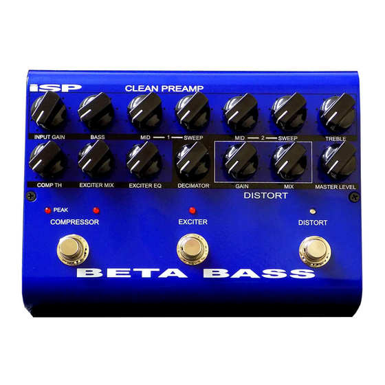
INTRODUCTION Congratulations on your purchase of the Beta Bass Pedal. The Beta Bass Pedal was designed to provide professional performance in a floor foot pedal. With a bass, treble plus two semi parametric mid band EQ circuits, studio compression, Bass Exciter, Bass Distortion plus on board Decimator II G-String noise reduction system. - Page 3 The BETA BASS pedal will only operate on a 9VAC power source, do not use any other power adaptor or damage may result. A balanced XLR output is also provided for...
- Page 4 The Beta Bass Pedal runs on an external 9VAC power adaptor and internally multiplies the 9VAC to produce a +/- 15 volt power supply. This means the Beta Bass provides true professional internal headroom not a typical 9 volt DC swing of other Bass guitar pedals.
-
Page 5: Input Gain
The Input Gain is right after the input buffer and is used to set the proper input level for the Beta Bass Pedal to keep the best possible headroom and noise floor performance. Connect the Bass Guitar to the input and adjust the Input Level control until the PEAK led above the COMPRESSOR switch flashes on transients or loud playing. -
Page 6: Treble Control
MIDRANGE BOOST/CUT CONTROL 1 AND 2 This control works in conjunction with the SWEEP frequency control. The MID and SWEEP controls work together to provide a semi-parametric tone control. When the MID control is set at 12:00 straight up there is no boost or cut in the MID frequency portion of the spectrum. - Page 7 If either the PREAMP or DISTORT circuits are switched on the Decimator circuit will be automatically switched into the signal path. The DECIMATOR noise reduction is a low level downward expander incorporating ISP’s patented TIME VECTOR PROCESSING. The Decimator is covered under multiple patents including...
-
Page 8: Master Level
A BRIEF EXPLANATION OF THE DECIMATOR NOISE REDUCTION SYSTEM Low Level Downward Expansion is performed by use of a high quality voltage controlled amplifier controlled by an RMS based audio level detection circuit. A Time Vector Processing circuit is used which varies the release response over a 1000 to 1 ratio and controls the release response of the Downward Expander. -
Page 9: Warranty And Service
Any damage resulting from the misuse or the failure to follow the precautions and instructions will void the warranty. In the event that the unit needs to be repaired, please return the unit to ISP Technologies directly. Simply repack the unit, send a copy of the original receipt, a note stating the problem, your...
Need help?
Do you have a question about the Beta Bass and is the answer not in the manual?
Questions and answers