Advertisement
Quick Links
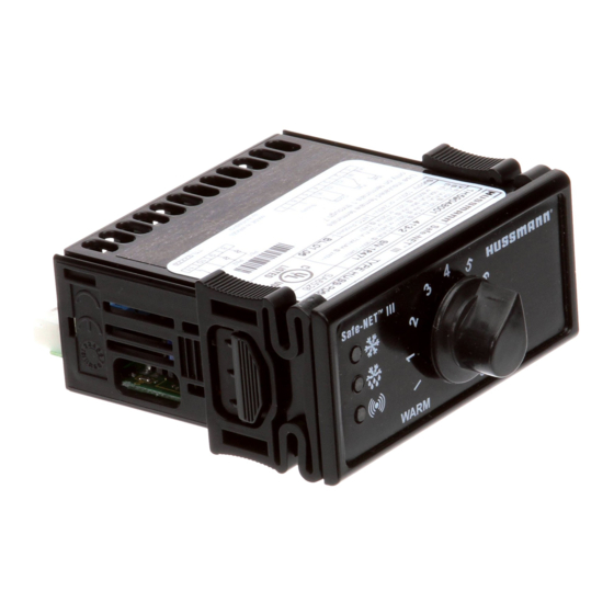
USER INSTRUCTIONS
Your refrigerated case uses a Hussmann Safe-NET
defrost controller to precisely maintain the temperature and prevent frost
buildup on the cooling coil. LEDs indicate when the compressor or
refrigeration is on, when the case is in a defrost cycle, if the temperature is
outside the desired range, or if there is a sensor failure. An adjustment knob
allows the temperature to be set within the configured range and can power
off the controller and compressor. Your controller has been custom-configured
to provide the best temperature and defrost control for your chilled or frozen
food.
The front of the controller has an adjustment knob and status LEDs. The back
of the controller has connections for sensors and switched equipment.
Temperature and
Defrost Controller
III temperature and
TM
1
Advertisement

Related Manuals for Hussmann Safe-NET III

Summary of Contents for Hussmann Safe-NET III
- Page 1 Temperature and Defrost Controller USER INSTRUCTIONS Your refrigerated case uses a Hussmann Safe-NET III temperature and defrost controller to precisely maintain the temperature and prevent frost buildup on the cooling coil. LEDs indicate when the compressor or refrigeration is on, when the case is in a defrost cycle, if the temperature is outside the desired range, or if there is a sensor failure.
- Page 2 Switches on the compressor or refrigeration valve for cooling. – Defrost relay: The Safe-NET III controller includes a defrost relay that switches on the optional evaporator fan during normal operation and switches on the defrost heater during a defrost cycle.
-
Page 3: Temperature Adjustment
Display The display includes three red LEDs and two digits for temperature, defrost status, and error codes. The three display LEDs are red, and their behavior matches the LEDs on the controller. Startup 1. Plug in the case. WARNING: The Off Position does not disconnect line voltage to the case, refrigeration unit, fan, or heater. -
Page 4: Manual Defrost
Alarms and Codes Flashing Temperature or Sensor Alarm LED, E1 or E2 If the Temperature or Sensor Alarm LED (red) on the controller and display is flashing, a temperature sensor has failed. The display shows E1 if the case sensor has failed or E2 if the evaporator sensor has failed. (See Alarms and Codes on page 7.) If the case sensor fails, depending on the configuration of your controller, refrigeration will run continuously, turn off, or repeat a duty cycle of a few... - Page 5 B. The defrost initiation may be delayed for as long as 2 minutes after step 3 is completed. The display will show “dF” once step 3 is completed, even with the protective delay timing out. The “dF” will display for a while after defrost has terminated, to allow the temperature to stabilize.
-
Page 6: Wiring Examples
WARNING: Before wiring the controller, make sure that the refrigeration unit, fan, heater, and controller are not connected to the electrical supply. Do not apply voltage to the digital input. Safe-NET III Controller Interface box and copy card TTL connector Defrost Termination Digital Input D.I. - Page 7 Your Case Configuration Average product temperature -10˚F. Factory Setting Knob position #5 Adjustment knob has Off position. Delay before compressor runs after startup. Delay Time 30 sec. Compressor operation if case sensor fails. Compressor On What the display shows during defrost? The case defrosts when the power is turned The method used to end defrost.
- Page 8 Hussmann Corporation Ingersoll Rand Climate Control Technologies 12999 St. Charles Rock Road Bridgeton, MO 63044 www.hussmann.com ©2009 Invensys Controls. All Rights Reserved.
Need help?
Do you have a question about the Safe-NET III and is the answer not in the manual?
Questions and answers