
Related Manuals for ASROCK N68C-GS4 FX


Summary of Contents for ASROCK N68C-GS4 FX
-
Page 1: User Manual
N68C-GS4 FX / N68C-S4 FX User Manual Version 1.0 Published October 2013 Copyright©2013 ASRock INC. All rights reserved. 1 1 1 1 1... - Page 2 (including damages for loss of profits, loss of business, loss of data, interruption of business and the like), even if ASRock has been advised of the possibility of such damages arising from any defect or error in the manual or product.
-
Page 3: Table Of Contents
8 / 8 64-bit / 7 / 7 64-bit / Vista Vista 64-bit With RAID Functions ....... 25 2.10 Untied Overclocking Technology ..........26 2.11 ASRock Home Cloud ..............27 3 . 3 . 3 . 3 . BIOS S BIOS S... - Page 4 3.4.8 USB Configuration ............51 Hardware Health Event Monitoring Screen ......... 52 Boot Screen ................53 3.6.1 Boot Settings Configuration ..........53 Security Screen ................. 54 Exit Screen ................55 4 . 4 . 4 . 4 . Software Support Software Support Software Support ...........
-
Page 5: Introduction Introduction
Introduction Introduction Introduction Thank you for purchasing ASRock N68C-GS4 FX / N68C-S4 FX motherboard, a reliable motherboard produced under ASRock’s consistently stringent quality control. It delivers excellent performance with robust design conforming to ASRock’s commitment to qual- ity and endurance. -
Page 6: Specifications
1.2 Specifications Platform - Micro ATX Form Factor A-Style - Home Cloud (N68C-GS4 FX) - Support for Socket AM3+ processors - Support for AM3 processors: AMD Phenom II X6 / X4 / X3 / X2 (except 920 / 940) / Athlon II X4 / X3 / X2 / Sempron... - Page 7 - Supports Energy Efficient Ethernet 802.3az - Supports PXE N68C-S4 FX: ® - Atheros AR8152, speed 10/100 Mb/s - Supports Wake-On-LAN - Supports PXE Rear Panel I/O I/O Panel - 1 x PS/2 Mouse Port - 1 x PS/2 Keyboard Port - 1 x Serial Port: COM1 - 1 x VGA Port - 4 x USB 2.0 Ports...
- Page 8 UCC (Unlock CPU Core) feature simplifies AMD CPU activation. As long as a simple switch of the BIOS option “ASrock UCC”, you can unlock the extra CPU core to enjoy an instant performance boost. When UCC feature is enabled, the dual-core or triple-core CPU will boost to the quad-core CPU,...
-
Page 9: Unique Features
ASRock OC Tuner. ASRock Instant Boot ASRock Instant Boot allows you to turn on your PC in just a few seconds, provides a much more efficient way to save energy, time, money, and improves system running speed for your system. It... - Page 10 - ASRock APP Charger. Simply install the APP Charger driver, it makes your iPhone charge much quickly from your computer and up to 40% faster than before. ASRock APP Charger allows you to quickly charge many Apple devices simulta-...
-
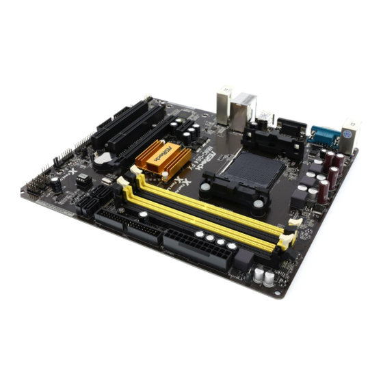
Page 11: Motherboard Layout
1.4 Motherboard Layout 1.4 Motherboard Layout 1.4 Motherboard Layout 1.4 Motherboard Layout 1.4 Motherboard Layout ATX12V1 CPU_FAN1 USB 2.0 T: USB2 B: USB3 USB 2.0 Top: T: USB0 RJ-45 B: USB1 Fast RAM Fast LAN NVIDIA GeForce 7025 / nForce PCIE1 630a SATAII_1... -
Page 12: I/O Panel
* There are two LED next to the LAN port. Please refer to the table below for the LAN port LED indications. LAN Port LED Indications ACT/LINK SPEED Activity/Link LED SPEED LED Status Description Status Description No Activity N68C-GS4 FX: Blinking Data Activity 10Mbps connection Orange 100Mbps connection LAN Port Green 1Gbps connection N68C-S4 FX: 10Mbps connection Orange... - Page 13 For Realtek ALC662 Audio Codec: To enable Multi-Streaming function, you need to connect a front panel audio cable to the front panel audio header. Please refer to below steps for the software setting of Multi-Streaming. For Windows ® After restarting your computer, you will find “Mixer” tool on your system. Please select “Mixer ToolBox”...
-
Page 14: Installation Installation
2. 2. 2. 2. 2. Installation Installation Installation Installation Installation This is a Micro ATX form factor motherboard. Before you install the motherboard, study the configuration of your chassis to ensure that the motherboard fits into it. Pre-installation Precautions Pre-installation Precautions Pre-installation Precautions Pre-installation Precautions Pre-installation Precautions... -
Page 15: Cpu Installation
2.1 CPU Installation 2.1 CPU Installation 2.1 CPU Installation 2.1 CPU Installation 2.1 CPU Installation Step 1. Unlock the socket by lifting the lever up to a 90 angle. Step 2. Position the CPU directly above the socket such that the CPU corner with the golden triangle matches the socket corner with a small triangle. -
Page 16: Installation Of Memory Modules (Dimm)
2.3 Installation of Memor 2.3 Installation of Memor 2.3 Installation of Memor y Modules (DIMM) 2.3 Installation of Memor 2.3 Installation of Memor y Modules (DIMM) y Modules (DIMM) y Modules (DIMM) y Modules (DIMM) This motherboard provides two 240-pin DDR2 (Double Data Rate 2) DIMM slots and two 240-pin DDR3 (Double Data Rate 3) DIMM slots, and supports Dual Channel Memory Technology. - Page 17 Installing a DIMM Installing a DIMM Installing a DIMM Installing a DIMM Installing a DIMM Please make sure to disconnect power supply before adding or removing DIMMs or the system components. Step 1. Unlock a DIMM slot by pressing the retaining clips outward. Step 2.
-
Page 18: Expansion Slots (Pci And Pci Express Slots)
2.4 Expansion Slots (PCI and PCI Express Slots) 2.4 Expansion Slots (PCI and PCI Express Slots) 2.4 Expansion Slots (PCI and PCI Express Slots) 2.4 Expansion Slots (PCI and PCI Express Slots) 2.4 Expansion Slots (PCI and PCI Express Slots) There are 2 PCI slots and 2 PCI Express slots on this motherboard. -
Page 19: Jumpers Setup
2.5 Jumpers Setup 2.5 Jumpers Setup 2.5 Jumpers Setup 2.5 Jumpers Setup 2.5 Jumpers Setup The illustration shows how jumpers are setup. When the jumper cap is placed on pins, the jumper is “Short”. If no jumper cap is placed on pins, the jumper is “Open”. -
Page 20: Onboard Headers And Connectors
2.6 Onboard Headers and Connectors 2.6 Onboard Headers and Connectors 2.6 Onboard Headers and Connectors 2.6 Onboard Headers and Connectors 2.6 Onboard Headers and Connectors Onboard headers and connectors are NOT jumpers. Do NOT place jumper caps over these headers and connectors. Placing jumper caps over the headers and connectors will cause permanent damage of the motherboard! •... -
Page 21: Front Panel Audio Header
USB 2.0 Headers USB_PWR Besides four default USB 2.0 ports on the I/O panel, there are (9-pin USB4_5) DUMMY three USB 2.0 headers on this (see p.11 No. 13) motherboard. Each USB 2.0 header can support two USB USB_PWR 2.0 ports. USB_PWR (9-pin USB6_7) (see p.11 No. - Page 22 System Panel Header This header accommodates PLED+ PLED- PWRBTN# several system front panel (9-pin PANEL1) functions. (see p.11 No. 16) DUMMY RESET# HDLED- HDLED+ Chassis Speaker Header Please connect the chassis speaker to this header. (4-pin SPEAKER 1) SPEAKER DUMMY (see p.11 No.
- Page 23 ATX 12V Power Connector Please note that it is necessary to connect a power supply with (4-pin ATX12V1) ATX 12V plug to this connector. (see p.11 No. 2) Failing to do so will cause power up failure. Chassis Intrusion Header This motherboard supports CASE OPEN detection feature that (2-pin CI1)
-
Page 24: Driver Installation Guide
B. Set the “SATA Operation Mode” option to [IDE]. STEP 2: Make a SATA / SATA2 Driver Diskette. A. Insert the ASRock Support CD into your optical drive to boot your system. B. During POST at the beginning of system boot-up, press <F11> key, and then a window for boot devices selection appears. -
Page 25: Vista Tm 64-Bit With Raid Functions
D. Then you will see these messages, Please insert a blank formatted diskette into floppy drive A: press any key to start Please insert a floppy diskette into the floppy drive, and press any key. E. The system will start to format the floppy diskette and copy SATA / SATA2 drivers into the floppy diskette. -
Page 26: 64-Bit / 7 / 7 64-Bit / Vista
/ Vista 64-bit OS on your system. When you see “Where do you want to install Windows?” page, please insert the ASRock Support CD into your optical drive, ® and click the “Load Driver” button on the left on the bottom to load the NVIDIA RAID ®... -
Page 27: Asrock Home Cloud
Atheros LAN chip, ASRock Home Cloud allows users to remotely wake up their computers via the internet by using a secondary device, such as a smartphone or tablet. Users may use Sunlogin to remotely wake up and control their computers, or they could wake up the computer then use any other preferred remote desktop application. -
Page 28: Configuring And Using Sunlogin
• Make sure that the "Shutdown Wake Up" and " SWOI" are enabled in Device Manager > Network Adapters > Qualcomm Atheros AR8171/8175 PCI-E Gigabit Ethernet Controller > Advanced. * " SWOI" may not appear in certain driver versions. 2.11.1.1 Configuring and Using Sunlogin Oray Sunlogin is a remote control software that lets you easily access and control the remote host that is installed with the Oray SunLogin Client software. - Page 29 Step 3 Click on Remote Client and follow the onscreen instructions to complete the installation. Step 4 Double-click the Sunlogin Remote Control icon in the Windows system tray. Step 5 Make sure that "Remote wakeup module" and "Remote control module" is set to On.
- Page 30 Installing Sunlogin control client Step 1 For Windows users: Download "Sunlogin Remote" from the Download section of sunlogin.oray. com and execute it. Log-in with your Sunlogin Account and Password. For iPad/iPhone users: Download “Sunlogin” from the App Store and install the app. Then fi ll in your Sunlogin Account and Password.
- Page 31 For Andriod mobile device users: Search “Sunlogin” in Google PLAY and then install the app. Then fi ll in your Sunlogin Account and Password. Using Remote Wakeup For Windows users: Select one Host (Offl ine with Gray power button) on the control client panel to wake up your home computer.
- Page 32 For Andriod mobile device users: Tap one Host (Offl ine with Blue power button ) on the Host List. Then tap the Power button to wakeup your home computer.
- Page 33 Using Remote Control For Windows users: Right-click on a Host (Online with Blue Windows logo) on the control client panel. Then key in your remote access password. For iPad/iPhone users: Tap one online machine on the Host List and fi ll in the Access password to start using remote control.
- Page 34 For Andriod mobile device users: Tap one online machine and fi ll in the Access password to start using remote control. Tutorial Video...
-
Page 35: Bios S
3. 3. 3. 3. 3. BIOS SETUP UTILITY BIOS SETUP UTILITY BIOS SETUP UTILITY BIOS SETUP UTILITY BIOS SETUP UTILITY 3.1 Introduction 3.1 Introduction 3.1 Introduction 3.1 Introduction 3.1 Introduction This section explains how to use the BIOS SETUP UTILITY to configure your system. The SPI Memory on the motherboard stores the BIOS SETUP UTILITY. -
Page 36: Navigation Keys
System Time [ :00:09] or [SHIFT-TAB] to System Date [Mon 10/28/2013] select a field. BIOS Version : N68C-GS4 FX P1.00 Use [+] or [-] to Processor Type : AMD Phenom (tm) II X4 910e configure system Time. Processor (64bit) Processor Speed... -
Page 37: Oc Tweaker Screen
Boot Failure Guard Count [Enabled] CPU/LDT Spread Spectrum [Enabled] PCIE Spread Spectrum [Enabled] SATA Spread Spectrum [Disabled] ASRock UCC [Auto] AMD Turbo Core Technology Select Screen AMD IO C-State Support [Enabled] Select Item CPU Active Core Control [Disabled] Enter Go to Sub Screen Processor Maximum Frequency x16.5 3300 MHZ... - Page 38 ASRock UCC ASRock UCC (Unlock CPU Core) feature simplifies AMD CPU activation. As long as a simple switch of the BIOS option “ASRock UCC”, you can unlock the extra CPU core to enjoy an instant performance boost. When UCC feature is...
- Page 39 Boot Failure Guard Count [Enabled] CPU/LDT Spread Spectrum [Enabled] PCIE Spread Spectrum [Enabled] SATA Spread Spectrum [Disabled] ASRock UCC [Auto] AMD Turbo Core Technology Select Screen AMD IO C-State Support [Enabled] Select Item CPU Active Core Control [Disabled] Enter Go to Sub Screen Processor Maximum Frequency x16.5 3300 MHZ...
- Page 40 Memory Timing BIOS SETUP UTILITY OC Tweaker Memory Timing [Unganged] Memory Controller Mode Power Down Enable [Disabled] Bank Interleaving [Auto] Channel Interleaving [Auto] CAS Latency (CL) [Auto] TRCD [Auto] [Auto] TRAS [Auto] Command Rate [Auto] Select Screen Select Screen [Auto] Select Item Select Item [Auto]...
- Page 41 Use this to adjust TWR values. The default value is [Auto]. TRFC Use this to adjust TRFC values. The default value is [Auto]. TRRD Use this to adjust TRRD values. The default value is [Auto]. TWTR Use this to adjust TWTR values. The default value is [Auto]. TRTP Use this to adjust TRTP values.
-
Page 42: Advanced Screen
3 . 4 3 . 4 3 . 4 3 . 4 3 . 4 Advanced Screen Advanced Screen Advanced Screen Advanced Screen Advanced Screen In this section, you may set the configurations for the following items: CPU Configuration, Chipset Configuration, ACPI Configuration, Storage Configuration, PCIPnP Configuration, Floppy Configuration, SuperIO Configuration and USB Configuration. -
Page 43: Cpu Configuration
AM2 Boost This option appears only when you adopt AM2 CPU. If you set this option to [Enabled], you will enable ASRock AM2 Boost function, which will improve the memory performance. The default value is [Disabled]. Please refer to caution 20 on page 11 for details. -
Page 44: Chipset Configuration
3 . 4 . 2 3 . 4 . 2 3 . 4 . 2 Chipset Configuration 3 . 4 . 2 3 . 4 . 2 Chipset Configuration Chipset Configuration Chipset Configuration Chipset Configuration BIOS SETUP UTILITY Advanced Chipset Settings Auto/Enable/Disable Onboard HD Audio. -
Page 45: Acpi Configuration
3 . 4 . 3 3 . 4 . 3 3 . 4 . 3 ACPI Configuration 3 . 4 . 3 3 . 4 . 3 ACPI Configuration ACPI Configuration ACPI Configuration ACPI Configuration BIOS SETUP UTILITY Advanced ACPI Settings Select auto-detect or disable the STR feature. -
Page 46: Storage Configuration
3 . 4 . 4 3 . 4 . 4 3 . 4 . 4 Storage Configuration 3 . 4 . 4 3 . 4 . 4 Storage Configuration Storage Configuration Storage Configuration Storage Configuration BIOS SETUP UTILITY Advanced Options Storage Configuration Disabled Enabled... - Page 47 TYPE Use this item to configure the type of the IDE device that you specify. Configu- ration options: [Not Installed], [Auto], [CD/DVD], and [ARMD]. [Not Installed]: Select [Not Installed] to disable the use of IDE device. [Auto]: Select [Auto] to automatically detect the hard disk drive. After selecting the hard disk information into BIOS, use a disk utility, such as FDISK, to partition and format the new IDE hard disk drives.
-
Page 48: Pcipnp Configuration
3 . 4 . 5 3 . 4 . 5 3 . 4 . 5 PCIPnP Configuration 3 . 4 . 5 3 . 4 . 5 PCIPnP Configuration PCIPnP Configuration PCIPnP Configuration PCIPnP Configuration BIOS SETUP UTILITY Advanced Value in units of PCI Advanced PCI / PnP Settings clocks for PCI device latency timer... -
Page 49: Floppy Configuration
3 . 4 . 6 3 . 4 . 6 3 . 4 . 6 Floppy Configuration 3 . 4 . 6 3 . 4 . 6 Floppy Configuration Floppy Configuration Floppy Configuration Floppy Configuration In this section, you may configure the type of your floppy drive. BIOS SETUP UTILITY Advanced Floppy Configuration... - Page 50 Parallel Port Mode Use this item to set the operation mode of the parallel port. The default value is [ECP+EPP]. If this option is set to [ECP+EPP], it will show the EPP version in the following item, “EPP Version”. Configuration options: [Normal], [Bi-Directional], and [ECP+EPP].
-
Page 51: Usb Configuration
3 . 4 . 8 3 . 4 . 8 3 . 4 . 8 USB Configuration 3 . 4 . 8 3 . 4 . 8 USB Configuration USB Configuration USB Configuration USB Configuration BIOS SETUP UTILITY Advanced USB Configuration To enable or disable the onboard USB controllers. -
Page 52: Hardware Health Event Monitoring Screen
3 . 5 3 . 5 3 . 5 3 . 5 3 . 5 Hardware Health Event Monitoring Screen Hardware Health Event Monitoring Screen Hardware Health Event Monitoring Screen Hardware Health Event Monitoring Screen Hardware Health Event Monitoring Screen In this section, it allows you to monitor the status of the hardware on your system, including the parameters of the CPU temperature, motherboard temperature, CPU fan speed, chassis fan speed, and the critical voltage. -
Page 53: Boot Screen
3 . 6 3 . 6 3 . 6 3 . 6 3 . 6 Boot Screen Boot Screen Boot Screen Boot Screen Boot Screen In this section, it will display the available devices on your system for you to configure the boot settings and the boot priority. -
Page 54: Security Screen
3 . 7 3 . 7 3 . 7 3 . 7 3 . 7 Security Screen Security Screen Security Screen Security Screen Security Screen In this section, you may set or change the supervisor/user password for the system. For the user password, you may also clear it. -
Page 55: Exit Screen
3 . 8 3 . 8 3 . 8 3 . 8 3 . 8 Exit Screen Exit Screen Exit Screen Exit Screen Exit Screen BIOS SETUP UTILITY Main OC Tweaker Advanced H/W Monitor Boot Security Exit Exit Options Exit system setup after saving the Save Changes and Exit changes. -
Page 56: Software Support Software Support
4.2.4 Contact Information Contact Information Contact Information Contact Information 4.2.4 4.2.4 Contact Information If you need to contact ASRock or want to know more about ASRock, welcome to visit ASRock’s website at http://www.asrock.com; or you may contact your dealer for further information.
Need help?
Do you have a question about the N68C-GS4 FX and is the answer not in the manual?
Questions and answers