Download Print this page
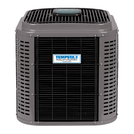
Tempstar CSA6 Installation Instructions Manual

Tempstar CSA6 Installation Instructions Manual

R?410a split system air conditioner

Advertisement

INSTALLATION INSTRUCTIONS
R−410A Split System Air Conditioner
These instructions must be read and understood completely before attempting installation.
IMPORTANT: Effective January 1, 2015, all split system and packaged air conditioners must be installed pursuant to
applicable regional efficiency standards issued by the Department of Energy.
DANGER, WARNING, CAUTION, and
NOTE
The
signal
words
CAUTION, and NOTE are used to identify levels of
hazard seriousness. The signal word DANGER is
only used on product labels to signify an immediate
hazard. The signal words WARNING, CAUTION,
and NOTE will be used on product labels and
throughout this manual and other manuals that may
apply to the product.
DANGER − Immediate hazards which will result in
severe personal injury or death.
WARNING − Hazards or unsafe practices which
could result in severe personal injury or death.
CAUTION − Hazards or unsafe practices which
may result in minor personal injury or product or
property damage.
NOTE − Used to highlight suggestions which will
result in enhanced installation, reliability, or
operation.

TABLE OF CONTENTS

. . . . . . . . . . . . . . . . . . . . . . . . . . .
Installation Requirements
. . . . . . . . . . . . . . . . . . . . . . . . . . . . . . . . . . . . .
Start−up Procedure
. . . . . . . . . . . . . . . . . . . . . . . . . . . . .
. . . . . . . . . . . . . . . . . . . . . . . . . . . . . . . .
. . . . . . . . . . . . . . . . . . . . . . . . . . . . . . . . .
CSA6, HSA6, TSA6
Safety Labeling and Signal Words
DANGER,
WARNING,
. . . . . . . . . . . . . . . . . . . . . . . .
. . . . . . . . . . . . . . . . . .
. . . . . . . .
Signal Words in Manuals
The signal word WARNING is used throughout this
manual in the following manner:
WARNING
!
The signal word CAUTION is used throughout this
manual in the following manner:
CAUTION
!
Signal Words on Product Labeling
Signal words are used in combination with colors
and/or pictures on product labels.
WARNING
!
2
ELECTRICAL SHOCK HAZARD
2
Failure to follow this warning could result in per-
2
sonal injury and/or death.
7
Before installing, modifying, or servicing system,
main electrical disconnect switch must be in the
8
OFF position. There may be more than 1 discon-
8
nect switch. Lock out and tag switch with a suit-
able warning label.
9
!
10
CUT HAZARD
Failure to follow this caution may result in per-
sonal injury
Sheet metal parts may have sharp edges or burrs.
Use care and wear appropriate protective clothing
and gloves when handling parts.
WARNING
CAUTION
421 01 5104 03
02/11/15

Advertisement

loading
Need help?

Need help?

Do you have a question about the CSA6 and is the answer not in the manual?

Questions and answers

Subscribe to Our Youtube Channel

Summary of Contents for Tempstar CSA6

  • Page 1: Table Of Contents

    INSTALLATION INSTRUCTIONS R−410A Split System Air Conditioner CSA6, HSA6, TSA6 These instructions must be read and understood completely before attempting installation. IMPORTANT: Effective January 1, 2015, all split system and packaged air conditioners must be installed pursuant to applicable regional efficiency standards issued by the Department of Energy.
  • Page 2: Safety Considerations

    INSTALLATION INSTRUCTIONS R−410A Split System Air Conditioner SAFETY CONSIDERATIONS Figure 1 Connecting Tube Installation Improper installation, adjustment, alteration, service, maintenance, or use can cause explosion, fire, electrical NOTE: Avoid contact between tubing and structure shock, or other conditions which may cause death, personal OUTDOOR WALL INDOOR WALL injury, or property damage.
  • Page 3 INSTALLATION INSTRUCTIONS R−410A Split System Air Conditioner For hurricane tie downs − contact your local distributor for Make Piping Connections details and PE (Professional Certification), if required by local WARNING authorities. On rooftop applications, mount on level platform or frame. PERSONAL INJURY AND ENVIRONMENTAL Place unit above a load−bearing wall and isolate unit and HAZARD...
  • Page 4 INSTALLATION INSTRUCTIONS R−410A Split System Air Conditioner Table 2 − Refrigerant Connections and Recommended Liquid and Vapor Tube Diameters (In.) RATED VAPOR up to 80 ft. (24.38 m)* LIQUID Connection and Tube Connection Rated Tube Diameter Diameter Diameter UNIT SIZE 18, 24, 30, 36, 42, 48 1−1/8...
  • Page 5 INSTALLATION INSTRUCTIONS R−410A Split System Air Conditioner Be sure field wiring complies with local and national fire, All wiring must be NEC Class 1 and must be separated from safety, and electrical codes, and voltage to system is within incoming power leads. limits shown on unit rating plate.
  • Page 6 INSTALLATION INSTRUCTIONS R−410A Split System Air Conditioner 4. Set room thermostat at desired temperature. Be sure Figure 7 Outdoor Coil Thermistor (OAT) Attachment set point is below indoor ambient temperature. 5. Set room thermostat to COOL and fan control to ON or OCT Thermistor must be AUTO mode, as desired.
  • Page 7: General Sequence Of Operation

    INSTALLATION INSTRUCTIONS R−410A Split System Air Conditioner With only 2 wires connected, the circuit board will be received within 2 minutes, the LED will be turned OFF until powered down whenever there is no call for cooling, and the the next valid communication. following will result: Amber Status Light S Compressor time delay is reduced from 5 minutes to 10...
  • Page 8: Troubleshooting

    INSTALLATION INSTRUCTIONS R−410A Split System Air Conditioner mode wire solenoid valve kit NASA401LS across LS and C contactor every 15 minutes. If the thermal protector closes, terminals . For operation in non−communicating mode wire (at the next 15 minute interval check), the unit will resume solenoid valve kit NASA401LS across C and Y terminals.
  • Page 9 INSTALLATION INSTRUCTIONS R−410A Split System Air Conditioner Example: 3 short flashes followed by 2 long flashes indicates a 32 code. Table 3 shows this to be low pressure switch open. Table 3 − Status Codes AMBER LED OPERATION FAULT Possible Cause and Action FLASH CODE Standby –...
  • Page 10 INSTALLATION INSTRUCTIONS R−410A Split System Air Conditioner Figure 9 Single Stage Control Board Specifications subject to change without notice. 421 01 5104 03...
  • Page 11 INSTALLATION INSTRUCTIONS R−410A Split System Air Conditioner Observer Communicating Wall Control Four−Wire Connection Wiring Diagrams Figure 10 (See Thermostat Installation Instructions for specific unit combinations) Variable Speed Wall Control Furnace/Fan Coil Outdoor Green Green Yellow Yellow DX− DX− DX− White White Optional Remote Room Sensor...
  • Page 12 INSTALLATION INSTRUCTIONS R−410A Split System Air Conditioner Non−Communicating Standard Thermostat Figure 12 2−Wire 24V Circuit Connections TPPICAL FURNACE A/C THERMOSTAT AIR CONDITIONER FAN COIL 24VAC HOT 24VAC COM W/W1 HEAT STAGE 1 HEAT STAGE 2 Y/Y2 INDOOR FAN FIEL INSTALLED JUMPER WIRE LEGEND 24V FACTORY WIRING 24V FIELD WIRING...
  • Page 13 INSTALLATION INSTRUCTIONS R−410A Split System Air Conditioner R−410A QUICK REFERENCE GUIDE • R−410A refrigerant operates at 50% − 70% higher pressures than R−22. Be sure that servicing equipment and replacement components are designed to operate with R−410A. • R−410A refrigerant cylinders are rose colored. •...
  • Page 14 INSTALLATION INSTRUCTIONS R−410A Split System Air Conditioner Specifications subject to change without notice. 421 01 5104 03 Copyright 2015 International Comfort Products Lewisburg, TN 37091 USA...

This manual is also suitable for:

Hsa6Tsa6