
Related Manuals for ETQ 170F

Summary of Contents for ETQ 170F
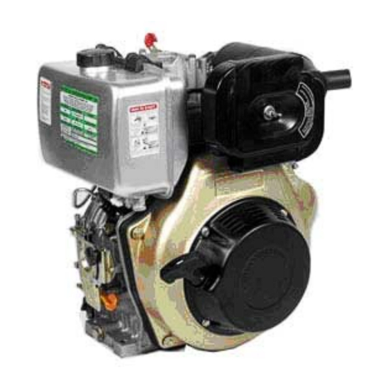
- Page 1 OWNER’S MANUAL AIR-COOLED DIESEL ENGINE 170F / FE / FS / FSE 178F / FE / FS / FSE 186F / FE / FS / FSE...
- Page 2 PREFACE The following manual is only a guide to assist you and is not a complete or comprehensive manual of all aspects of maintaining and repairing your engine. The engine you have purchased is a complex piece of machinery. We recommend that that you consult with a dealer if you have doubts or concerns as to your experience or ability to properly maintain or repair your engine.
-
Page 3: Table Of Contents
TABLE OF CONTENTS Page number Safety Precautions Chapter 1 Technical Specifications and Data 1-1 Technical Specifications 1-2 Overall Dimensions and Installation Conditions 1-2.1 Belt wheel and engine clearance requirements 1-2.2 Crankshaft driving angle conditions 1-2.3 Engine electrical system 1-3 Diesel engine shaft specifications 1-4 Diesel engine part names 1-5 Valve timing, initial angle of fuel delivery and valve clearances 1-5.2 Initial angle of fuel delivery... -
Page 4: Safety Precautions
SAFETY PRECAUTIONS Please be sure to follow each instruction carefully EXHAUST PRECAUTIONS • Never inhale the exhaust gases, it contains carbon monoxide, a colorless, odorless and extremely dangerous gas which can cause unconsciousness or death • Never operate the engine indoors or in a poorly ventilated area, such as a tunnel or cave, etc. - Page 5 FIRE PREVENTION • Never operate the engine while smoking or near an open flame. • Never use the engine around dry brush, twigs, cloth-rags, or other flammable materials. • Keep the engine at least 3 feet (1 meter) away from buildings or other structures.
- Page 6 SURROUNDINGS • Operate the engine on a table or level surface free of small rocks and loose gravel. • Operate the engine on a level surface. If the engine is tilted, fuel may spill from the gas tank. NOTE: Operating the engine at a steep incline may cause the engine to seize up due to improper lubrication even when the oil level is a maximum.
-
Page 7: Chapter 1 Technical Specifications And Data
Chapter 1 Technical Specifications and Data 1-1 Technical specifications in English Units Model 170F 178F 186F Item Type Single vertical cylinder, 4-stroke, air-cooled, direct injection Bore x Stroke (in.) 2.76 x 2.17 3.01 x 2.44 3.39 x 2.76 Displacement (cu. in.) 13.36... - Page 8 Technical specifications in SI units Model 170F 178F 186F Item Type Single vertical cylinder, 4-stroke, air-cooled, direct injection Bore x Stroke (mm) 70 x 55 78 x 62 86 x 70 Displacement (cc) Speed (rpm) 3600 3600 3600 Output Continuous 2.98...
- Page 9 1-2 Overall engine dimensions Installation Conditions There must be a tight stationary foundation for the diesel engine to avoid vibrations or movement when the engine is running. For prolonged engine life, consider using some type of motor mount. Make sure that the centering position of the output shaft is properly aligned.
- Page 10 Verify that the dimensions of the hole on the belt wheel and keyway shaft match or correspond with each other. Also make sure that the bolt of the engine shaft is tightened to the proper torque specifications. When the engine is matched with other belt driven machines, the total desired belt distance traveled by the driven wheel must equal the total distance traveled by the driver wheel.
- Page 11 Fig 1-2. Allowed tilt angles. 1-2.3 Please contact our dealers about the electric circuits involved with this engine. We recommend the use of accumulators rated at 20 hours shown in table 1-2. Table 1-2. Model Units: (amp-hours) 170F 18~24 178F 24~26 186F 36~45...
-
Page 12: Diesel Engine Shaft Specifications
Diesel Engine shaft specifications units: mm... - Page 13 Sizes of PTO flanges Diesel Engine Power Curves 1-4 Names of Diesel Engine Parts...
-
Page 14: Valve Timing, Initial Angle Of Fuel Delivery And Valve Clearances
1-5 Valve timing, initial angle of fuel delivery and valve clearances. Units: Degrees Table 1-3. 1-5.2 Initial angle of fuel delivery Units: Degrees Table 1-4 1-5.3 Valve Clearances Table 1-5 1-6 Temperature ranges for exhaust and injection pressure specifications... - Page 15 1-7 Torque specifications for various engine nuts and bolts Table 1-7. Torque specifications in SI units Units: N m...
-
Page 16: Chapter 2 Diesel Engine Operation Procedures
CHAPTER 2 DIESEL ENGINE OPERATION 2-1 Please pay close attention for safe operation of the diesel engine. The fuel used must be filtered by silk fabric or settled for 24 hours before it is used in the engine. Never add oil to the crankcase when the engine is running. Keep flammable and combustible goods away from engine while engine is running. - Page 17 Oiling plug: In winter, if it is difficult to start the Compression release lever: engine, pull the plug out and fill 2cc of lube oil Push the lever down into the hole and then put the plug back in to start the engine place.
- Page 18 If your engine is still relatively new, follow the break in procedure. The life of the engine will shorten if it is overloaded during its break in period. For the first 20 hours, the engine must be started and stopped according to the test run method. Avoid overloading the engine Change the engine oil regularly.
-
Page 19: Starting The Diesel Engine
2-3 Starting the Diesel Engine 2-3.1 Recoil Starting Note: When the engine is running, do not pull the recoil handle, otherwise the engine may be damaged. -
Page 21: 2-3.3 Cold Starting
2-3.2 Diesel engine with electric starter system Starting The preparation of the diesel engine for the electric starting system is the same as the manual recoil type. Open the fuel cock. Set the speed governor lever to the start position. Turn the start switch clockwise to the “Start”... - Page 22 Warning: Never use flammable liquids as fuel, such as gasoline etc. Also, never take away the air cleaner for easy starting of the engine, doing so may cause explosions from the intake gases. Never take the oil plug unless you’re planning on filling the oil. If the plug is not in place, rain, dust, and other impurities may be sucked into the engine causing serious damage to the engine parts.
-
Page 23: Running And Stopping The Diesel Engine
2-4 Running and stopping of the Diesel Engine 2-4.1 Running the Diesel engine Preheat the engine for three minutes at no load. Set the speed governor lever to the desired speed. Use the speed governor lever to control the speed of the engine. Never loosen or readjust the speed limiting screw and the 2-4.2 Checks on the engine while the engine is running. - Page 24 If the engine comes with an electric starter, turn the starting switch to the “Off” position. Pull the recoil handle slowly until pressure is felt by your hand, this means the piston is on the compression stroke; where the intake and exhaust valves are closed and then let the handle recoil back into the engine.
-
Page 25: Chapter 3 Technical Maintenance Of Diesel Engine
CHAPTER 3. TECHNICAL MAINTENANCE OF DIESEL ENGINE 3-1 Daily checks and maintenance Check the oil level of the engine to see whether it is between the upper and lower limits. Check to see whether there any oil leaks within the engine. Keep the engine clean by cleaning up the dirt and other greasy deposits on the engine. -
Page 27: Storing The Engine For Long Periods Of Time
The core of the air filter may become dirty from various impurities. If this occurs, the performance of the engine will decrease because the amount of air entering the combustion chamber is incorrect. Also, because the amount of air is incorrect, the amount of fuel entering also becomes incorrect leading to an overall incorrect air/fuel mixture. - Page 28 Take the rubber plug off the cover of the rocker shaft and put about 2cc of lubricant into it and put the plug back in place. The figure below shows where to access the plug. For recoil starting engines, push the decompression lever down and pull the recoil starter two or three times.
-
Page 29: Chapter 4 Part Listings
CHAPTER 4 PART LISTINGS Diesel Engine Exploded View... -
Page 30: Engine Block
4-1 Engine Block Table 4-1. Please refer to Fig 4-1 for illustration Number Part Number Name of Part Qty each set KS1710626 Bolt M10 x 20 (GB5787-86) KS 17138 Starter motor hole cover KS 70-1704901 KS 78-1704902 Cylinder head nuts (long) KS 86-1704903 KS 70-1705001 KS 78-1705002... - Page 31 KS 1710010 Needle bearing 7941/15 KS 70-1710006 Ball bearing 306 (GB/T276-94) KS 78-1710007 Ball bearing 307 (GB/T276-94) KS 86-1710008 Ball bearing 308 (GB/T276-94) KS 70-1704601 KS 78-1704602 Crankcase cover gasket KS 86-1704603 KS 70-1710002 Bearing 205 (GB/T276-94) KS 78-1710003 Bearing 206 (GB/T276-94) KS 86-1710004 Bearing 207 (GB/T276-94) KS 1711111...
- Page 32 Fig 4-1. Exploded view of engine block assembly...
-
Page 33: Cylinder Head Assembly
4.2 Cylinder head Assembly Table 4-2. Part listing for cylinder head assembly. Please refer to Fig 4-2 Code Names of Parts Qty each set KS 70/78-1710755 M6 x 55 Flanged Bolt (GB5789-86) KS 86-1710730 M6 x 70 Flanged Bolt (GB5789-86) KS 17142 Oiling hole plug KS 17139... - Page 34 KS 86-1702503 KS 70-1702502 KS 78-1702602 Exhaust valve KS 86-1702605 KS 1710103 M6 (GB6177-86) Nut KS 1717302 Fuel injector pressure plate KS 1724502 Fuel injector gasket KS 70-1712201 AM 6 x 42 Fuel injector bolt KS 78-1712201 AM 6 x 42 Fuel injector bolt KS 86-17122 Fuel injector bolt (long) KS 17141...
- Page 35 Fig 4-2. Exploded view of cylinder head...
-
Page 36: Piston Connecting Rod And Crankshaft Balancing Mechanism
4-3 Piston connecting rod and crankshaft balancing mechanism Table 4-3. Please refer to Fig 4-3 for a complete illustration of the parts. Code Name of Part Qty each set KS70-1701403 KS 78-1701402 Piston Rings KS 86-1701404 KS 70-1701601 Retainer clip of Piston pin Dia. 19mm KS 78-1701602 Retainer clip of Piston pin Dia. - Page 37 KS 70-1707801 Balancing Shaft Driving Gear KS 78-1707802 KS 86-1707803 KS 70-1704400 KS 78-1704404 Flywheel KS 86-1704409 KS 70/78-17156 Flywheel nut gasket KS 86-1715601 KS 70/78-17155 Flywheel nut KS 86-1715501 KS 70-1704501 KS 78-1704502 Flywheel ring gear (for electric starter) KS 86-1705504 KS 1704705 Sleeve of fuel pump rod...
- Page 38 Fig 4-3. Exploded view of Piston / Crank Assembly...
-
Page 39: Fuel System Parts
4-4 Fuel System Parts Table 4-4. Fuel system parts; please refer to Fig 4-4 for a complete illustration. Code Name of part Qty each set KS 1710745 M8 x 45 (GB5787-86) Bolt KS 17185 Upper fuel tank bracket fastener KS 1710208 Flat washer 8 (GB97.1-85) KS 70-1705801 KS 78-1705802... - Page 40 Fig 4-4. Exploded view of fuel tank parts...
-
Page 41: Oil And Speed Control System
4-5 Oil and speed control system Table 4-5. Please refer to Fig 4-5 for a complete illustration. Code Name of part Qty each set KS 70-1710712 M6 x 12 (GB5787-86) Bolt KS 70-17187 Oil filter cover KS 70-17188 Oil filter cover gasket KS 70-1711314 Sealing Ring 20 x 2.5 KS 78/86-1711316... - Page 42 KS 78-17160 Speed-control spring KS 86-1716001 KS 1710645 M6 x 45 (GB6172-86) Bolt KS 1710111 M10 x 1.25 Nut KS 1706701 FG Lever KS 1706901 FG governor spring KS 1710714 M6 x 14 (GB5789-86) Bolt KS 1710106 M6 (GB39-88) Nut KS 1716801 Washer KS 1730720...
- Page 43 Fig 4-5. Lubrication and speed control system...
-
Page 44: Cooling And Recoil Starting System
4-6 Cooling and recoil starting system Table 4-6. Please refer to Fig 4-6 for illustration. Code Name of part Qty each set KS 70-1703401 KS 78-1703402 Recoil case assembly KS 86-1703404 KS 78-1703404 178FS case assembly KS 1710708 M6 x 8 (GB5787-86) KS 70-1703501 KS 78-1703502 Recoil starter rope... - Page 45 KS 78-17145 Collar KS 70/86-17145 KS 78-17143 Shock absorber KS 70/86-17143 KS 17144 Shock pads KS 78/86-17127 Shock isolator KS 78/86-17129 Collar KS 78/86-17128 KS 70-1700401 KS 78-1700402 Wind leading plate KS 86-1700403 KS 70-1710712 M6 x 12 (shaped piece) Bolt KS 78-1710718 M6 x 18 (shaped piece) Bolt KS 86-1710614...
- Page 46 Fig 4-6. Exploded view of cooling and recoil starting system.
-
Page 47: Air Cleaner And Silencer System
4-7 Air cleaner and silencer system Table 4-7. Please refer to Fig 4-7 for a complete illustration. Code Name of part Qty each set KS 70-1703101 KS 78-1703102 Intake pipe gasket KS 86-1703103 KS 70-1703001 KS 78-1703002 Intake pipe KS 86-1703003 KS 70/78-17175 Air cleaner gasket KS 86-1717501... - Page 48 KS 70/78-17182 Air filter shock absorber KS 86-1720106 KS 17177 KS 70/78-1710107 M6 butterfly nut KS 85-1710109 M8 butterfly nut Fig 4-7. Exploded view of muffler assembly...
-
Page 50: Chapter 5 Engine Troubleshooting
CHAPTER 5 ENGINE TROUBLESHOOTING 5-1 Engine is not starting Possible Cause Remedy Weather is cold. Engine oil may have become Put engine oil into crankcase after preheated. Put overly adhesive. engine oil into the inlet manifold. Disconnect the belts to the engine and run engine under no load conditions until the engine becomes hot. -
Page 51: Engine Stops Automatically
Possible Cause Remedy Fuel system clogged. Clogged fuel line or clogged Clean fuel filter and fuel pipe. Check the fuel fuel filter. switch, it should be opened fully. Fuel pump is bad. Service or change the damaged parts of the fuel pump. - Page 52 OWNER’S MANUAL Air-cooled diesel engine generator set DG4LE / DG6LE...
- Page 53 • AC and DC outputs • Low oil pressure sensor The ETQ air-cooled diesel generators are widely used when electrical power is scarce. Our generators provide a portable mobile solution in supplying power for field operations during project construction. Some other known applications include pipeline construction and metal welding when electrical power is not available.
- Page 54 TABLE OF CONTENTS Page number Overall view of the generator set Chapter 1 Technical Specifications and Data 1-1 Technical specifications and data 1-2 Basic operating parameters 1-3 General dimensions and overview of the generators 1-4 Electric wiring diagrams for various models of generators Chapter 2 Operating the Diesel Generator 2-1 Main points of safety during operation of the generator 2-2 Preparation before operation...
- Page 55 1. Overall view of DG3LE series 3. Overall view of DG6LE series 2. Overall view of DG4LE series 4. Overall view of DG6LE-3P series...
-
Page 56: Chapter 1 Technical Specifications And Data
CHAPTER 1. TECHNICAL SPECIFICATIONS AND DATA Technical specifications in SI units Item Model 3LE Series 4LE Series 6LE Series 6LE-3P Series Generator Type Single phase AC generator Three phase Frequency (Hz) Rated power (Kw) Cont. power (kW) Voltage (AC) (V) 120 / 240 Voltage (AC) (V) 420/240... - Page 57 Technical specifications in English units Item Model 3LE Series 4LE Series 6LE Series 6LE-3P Series Generator Type Single phase AC generator Three phase Frequency (Hz) Rated power (HP) 3.75 5.36 8.04 Cont. power (HP) 3.49 4.69 7.37 6.04 Voltage (AC) (V) 120 / 240 Voltage (AC) (V) 420/240...
-
Page 58: Basic Operating Parameters
1-2 Basic operating parameters 1-1.1 Under the given conditions, the generator will output the specified power in the table listed below. Table 1. Height above sea level (ft) Ambient temperature ( +60 (+20 <3280.8 (<1000 m) 41~104 (5-40 1-3 General dimensions and overview of the generators 1-3.1 General dimensions of the LN series generators... -
Page 59: Electric Wiring Diagrams For Various Models Of Generators
1-4 Electric wiring diagrams for various models of generators... -
Page 62: Chapter 2 Operating The Diesel Generator
CHAPTER 2 OPERATING THE DIESEL GENERATOR 2-1 General main points of safety during operation of the generator set. In order to operate the generator set safely, please follow all the instructions provided in this manual carefully. Doing so otherwise may lead to accidents and or equipment damage. - Page 63 Fig 2-1 Fig 2-2 Note: When connecting devices to the generator, make sure all other devices are rated lower than the generators output. Any generator socket should not be overloaded over its regulated limit 2-1.5 Other safety points Before operating this generator, all operators should have a good knowledge of how to break the circuit if any accidents occur.
-
Page 64: Preparation Before Operation
2-2 Preparation before operation 2-2.1 Fuel choices and fuel treatment Air filter element Fuel tank Use only light diesel fuel. The fuel Do not wash the air filter. The should be filtered clean. Never let element is made of dry material, dust and water mix with fuel in the which does not permit washing. - Page 65 2-2.2 Filling engine oil Remove the dipstick from the engine Make sure the generator is on level ground, and fill the engine with 15W40 engine oil. Put the dipstick back into the hole to check the engine oil level. Engine oil is the most important factor in determining the life of your generator engine. If you use poor engine oil or if you don’t change the oil regularly, the piston and cylinder will wear easily or seize up.
- Page 66 2-2.3 Checking the air filter (1) Loosen the butterfly nut, take the cover of the air filter off and take the air filter element out. (Note: Only certain welder generator sets have an electric fan incorporated on them.) Butterfly nut Before starting the generator, make sure the air switch is in the “Off”...
-
Page 67: Checking The Operation Of The Diesel Engine
When you purchase a brand new 2-3.1 Low-pressure alarm system. engine, the engine must be ETQ diesel engines have a low- properly broken in. The break in pressure sensor system where if period is about 20 hours. the oil pressure drops too low,... - Page 68 position. 1. Insert key into ignition and put it in the “off” position. 2. Put the speed handle in the “Run” position. 3. Turn the start switch clockwise to the “START” position; (to set the silent type, first turn it clockwise to (3) Pull the recoil starter handle the “RUN”...
- Page 69 Important Notice: All of our units come with a dry battery for shipping safety purposes. In order to get your generator started for the first time; the battery must be filled with battery acid which can be purchased at a local automotive supply store and slowly charged (trickle charged) for a day.
-
Page 70: Procedures For Starting The Generator Set
2-5 Procedures for starting the generator set This procedure applies to the L series recoil starting style models. -
Page 72: Proper Operation Of The Generator Set
2-6.2 Checks during engine operation 2-6 Proper operation of the generator 2-6.1 Operating the diesel engine 1. Check to see if there are 1. Pre-heat the diesel engine for abnormal noises. 3 minutes under no load 2. Check to see if the conditions. - Page 73 voltage from the socket of the technical specifications of power supply can be output. what the generator can 3. When connecting devices to output. In order to reset the the generator, make sure to generator after overdrawn connect these devices in power, let it sit for several order.
-
Page 74: Stopping The Generator
6. Finally, pull slowly on the 2-8 Stopping the generator 1. Take the electrical load off recoil handle until you feel the generator. resistance (this is when the 2. Put the speed handle in the piston is on the compression “RUN”... -
Page 75: Chapter 3 Maintenance
CHAPTER 3 MAINTENANCE 3-1 Maintenance schedules Keeping your generator well maintained will prolong the life of your generator. Everything needs to be checked including the diesel engine, generator, control cabinet, and frame. For overhauling procedures, please refer to the instruction manual of the relative subassembly. - Page 76 3-1.1 Changing the engine oil (every 3-1.3 Fuel filter maintenance 100 hours) 1. The fuel filter should be cleaned Take the oil cover off. Remove the oil often to keep the engine running drain plug when the diesel engine is still at maximum performance.
-
Page 77: Storing For Long Periods Of Time
3-2 Storing for long periods of time If your generator needs to be stored for long periods of time, the following preparations should be made. 1. Start the diesel engine for 3 minutes then stop it. 2. When the engine is still hot, change the engine oil with new engine oil of the proper grade. -
Page 78: Chapter 4 Troubleshooting
CHAPTER 4 TROUBLESHOOTING 4-1 Troubleshooting procedures If you are still having trouble, please contact with your nearest dealer or with our company directly if necessary. 4-2 Questions and doubts If you do not understand anything or have any questions, please feel free to contact your local dealer or with our company directly. -
Page 79: Chapter 5 Generator Parts Diagrams And Listings
Figure 5-2. Overall view of engine generator assembly Table 5-1. Please refer to figure 5-2 for illustration Number Part Description Quantity Part Number (4LE / 6LE) ETQ series diesel engine ETQ4LE1 / ETQ6LE1 Starter Motor ETQ4LE2 / ETQ6LE2 Flywheel generator ETQ4LE3 / ETQ6LE3... - Page 80 Figure 5-3. Exploded view of frame assembly...
- Page 81 Table 5-2. Please refer to figure 5-3. Number Part Description Quantity Part Number (4LE / 6LE) M6 x 25 Bolt ETQ4LE17 / ETQ6LE17 M6 Flat washer ETQ4LE18 / ETQ6LE18 Shock absorber ETQ4LE19 / ETQ6LE19 Washer ETQ4LE20 / ETQ6LE20 M6 Nut ETQ4LE21 / ETQ6LE21 Engine cover ETQ4LE22 / ETQ6LE22...
- Page 82 Figure 5-4. Electric panel parts drawing Table 5-3. Please refer to Figure 5-4 Number Part Description Quantity Part Number (4LE /6LE) Positive DC port ETQ4LE69 / ETQ6LE69 Negative DC port ETQ4LE70 / ETQ6LE70 Grounded bolt ETQ4LE71 / ETQ6LE71 Bolt ETQ4LE72 / ETQ6LE72 Large Nut ETQ4LE73 / ETQ6LE73 Bolt...
- Page 83 Figure 5-5. Generator head assembly Table 5-4. Please refer to figure 5-5 Number Part Description Quantity Part Number (4LE / 6LE) Front end cover ETQ4LE96 / ETQ6LE96 Diode ETQ4LE97 / ETQ6LE97 M4 x 8 Bolt ETQ4LE98 / ETQ6LE98 Fan Blade ETQ4LE99 / ETQ6LE99 Bearing ETQ4LE100 / ETQ6LE100...
- Page 84 Figure 5-6. Fuel system components Table 5-5. Please refer to figure 5-6. Number Part Description Quantity Part Number (4LE / 6LE) Fuel Cap ETQ4LE111 / ETQ6LE111 Seal ETQ4LE112 / ETQ6LE112 Filtering cup ETQ4LE113 / ETQ6LE113 M5 x 10 screw ETQ4LE114 / ETQ6LE114 Fuel lever indicator ETQ4LE115 / ETQ6LE115 M6 x 25 Bolt...
-
Page 85: Limited Warranty
LIMITED WARRANTY Eastern Tools & Equipment, Inc. will repair or replace, free of charge, any part or parts of the generator that are defective in material or workmanship or both. Transportation charges on parts submitted for repair or replacement under this Warranty must be borne by purchaser. This warranty is effective for the time period and subject to the conditions provided for in this policy. - Page 86 Improper maintenance: The life of an engine or your equipment depends upon the conditions under which it operates, and the care it receives. Some applications, such as tillers, pumps, and rotary movers, are very often used in dusty or dirty conditions, which can cause what appears to be premature, wear.
-
Page 87: List For Comments From Users
List for comments from users Date of Manufacture Name of user Model Number Address of user Occupation Place of purchase Packaging conditions Operating conditions Parts Conditions Malfunction problem Opinions or suggestions Note: Please mail the above card to: Eastern Tools & Equipment, Inc. 12220 Rivera Rd, Suite B Whittier, CA 90606... -
Page 88: Appendix
Appendix: 1. Attached list of tools, fittings, and subassemblies Order No. Name Remarks Air-cooled diesel welder and generator set Plastic cover Plug and power supply 2. Attached technical documents Order No. Name Remarks Air cooled diesel welder and generator manual Diesel engine instruction manual Diesel engine parts listing Certificate of Quality... - Page 89 EASTERN TOOLS & EQUIPMENT, INC. TEL: 1-626-960-6299 FAX: 1-626-960-6244 WEB SITE.http://easterntools.com...
Need help?
Do you have a question about the 170F and is the answer not in the manual?
Questions and answers
Yes, I have a question. I want to know the vacuum pressure in the 186FA Diesel Engine Muffler. Thanks in advance.