
Related Manuals for ETQ 170F

Summary of Contents for ETQ 170F
- Page 1 OWNER’S MANUAL AIR-COOLED DIESEL ENGINE 170F / FE / FS / FSE 178F / FE / FS / FSE 186F / FE / FS / FSE...
- Page 2 PREFACE Thank you for purchasing products from Eastern Tool & Equipment, INC. The following manual is only a guide to assist you and is not a complete or comprehensive manual of all aspects of maintaining and repairing your engine. The engine you have purchased is a complex piece of machinery.
-
Page 3: Table Of Contents
TABLE OF CONTENTS Page number Safety Precautions Chapter 1 Technical Specifications and Data 1-1 Technical Specifications 1-2 Overall Dimensions and Installation Conditions 1-2.1 Belt wheel and engine clearance requirements 1-2.2 Crankshaft driving angle conditions 1-2.3 Engine electrical system 1-3 Diesel engine shaft specifications 1-4 Diesel engine part names 1-5 Valve timing, initial angle of fuel delivery and valve clearances 1-5.2 Initial angle of fuel delivery... -
Page 4: Safety Precautions
SAFETY PRECAUTIONS Please be sure to follow each instruction carefully EXHAUST PRECAUTIONS • Never inhale the exhaust gases, it contains carbon monoxide, a colorless, odorless and extremely dangerous gas which can cause unconsciousness or death • Never operate the engine indoors or in a poorly ventilated area, such as a tunnel or cave, etc. - Page 5 FIRE PREVENTION • Never operate the engine while smoking or near an open flame. • Never use the engine around dry brush, twigs, cloth-rags, or other flammable materials. • Keep the engine at least 3 feet (1 meter) away from buildings or other structures.
- Page 6 SURROUNDINGS • Operate the engine on a table or level surface free of small rocks and loose gravel. • Operate the engine on a level surface. If the engine is tilted, fuel may spill from the gas tank. NOTE: Operating the engine at a steep incline may cause the engine to seize up due to improper lubrication even when the oil level is a maximum.
-
Page 7: Chapter 1 Technical Specifications And Data
Chapter 1 Technical Specifications and Data 1-1 Technical specifications in English Units Model 170F 178F 186F Item Type Single vertical cylinder, 4-stroke, air-cooled, direct injection Bore x Stroke (in.) 2.76 x 2.17 3.01 x 2.44 3.39 x 2.76 Displacement (cu. in.) 13.36... - Page 8 Technical specifications in SI units Model 170F 178F 186F Item Type Single vertical cylinder, 4-stroke, air-cooled, direct injection Bore x Stroke (mm) 70 x 55 78 x 62 86 x 70 Displacement (cc) Speed (rpm) 3600 3600 3600 Output Continuous 2.98...
-
Page 9: Overall Dimensions And Installation Conditions
1-2 Overall engine dimensions Installation Conditions (1) There must be a tight stationary foundation for the diesel engine to avoid vibrations or movement when the engine is running. For prolonged engine life, consider using some type of motor mount. (2) Make sure that the centering position of the output shaft is properly aligned. -
Page 10: 1-2.1 Belt Wheel And Engine Clearance Requirements
(3) Verify that the dimensions of the hole on the belt wheel and keyway shaft match or correspond with each other. Also make sure that the bolt of the engine shaft is tightened to the proper torque specifications. (4) When the engine is matched with other belt driven machines, the total desired belt distance traveled by the driven wheel must equal the total distance traveled by the driver wheel. -
Page 11: 1-2.2 Crankshaft Driving Angle Conditions
Fig 1-2. Allowed tilt angles. 1-2.3 Please contact our dealers about the electric circuits involved with this engine. We recommend the use of accumulators rated at 20 hours shown in table 1-2. Table 1-2. Model Units: (amp-hours) 170F 18~24 178F 24~26 186F 36~45... -
Page 12: Diesel Engine Shaft Specifications
Diesel Engine shaft specifications units: mm... -
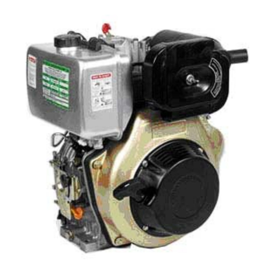
Page 13: Diesel Engine Part Names
Sizes of PTO flanges Diesel Engine Power Curves 1-4 Names of Diesel Engine Parts... -
Page 14: Valve Timing, Initial Angle Of Fuel Delivery And Valve Clearances
1-5 Valve timing, initial angle of fuel delivery and valve clearances. Units: Degrees Table 1-3. 1-5.2 Initial angle of fuel delivery Units: Degrees Table 1-4 1-5.3 Valve Clearances Table 1-5 1-6 Temperature ranges for exhaust and injection pressure specifications... -
Page 15: Various Engine Torque Specifications
1-7 Torque specifications for various engine nuts and bolts Table 1-7. Torque specifications in SI units Units: N m... -
Page 16: Chapter 2 Diesel Engine Operation Procedures
CHAPTER 2 DIESEL ENGINE OPERATION 2-1 Please pay close attention for safe operation of the diesel engine. 1. The fuel used must be filtered by silk fabric or settled for 24 hours before it is used in the engine. Never add oil to the crankcase when the engine is running. 2. - Page 17 Oiling plug: In winter, if it is difficult to start the Compression release lever: engine, pull the plug out and fill 2cc of lube oil Push the lever down into the hole and then put the plug back in to start the engine place.
- Page 18 If your engine is still relatively new, follow the break in procedure. The life of the engine will shorten if it is overloaded during its break in period. For the first 20 hours, the engine must be started and stopped according to the test run method. Avoid overloading the engine Change the engine oil regularly.
-
Page 19: Starting The Diesel Engine
2-3 Starting the Diesel Engine 2-3.1 Recoil Starting Note: When the engine is running, do not pull the recoil handle, otherwise the engine may be damaged. -
Page 21: 2-3.2 Electric Starter
2-3.2 Diesel engine with electric starter system (1) Starting The preparation of the diesel engine for the electric starting system is the same as the manual recoil type. a. Open the fuel cock. b. Set the speed governor lever to the start position. c. - Page 22 Warning: Never use flammable liquids as fuel, such as gasoline etc. Also, never take away the air cleaner for easy starting of the engine, doing so may cause explosions from the intake gases. Never take the oil plug unless you’re planning on filling the oil. If the plug is not in place, rain, dust, and other impurities may be sucked into the engine causing serious damage to the engine parts.
-
Page 23: Running And Stopping The Diesel Engine
2-4 Running and stopping of the Diesel Engine 2-4.1 Running the Diesel engine (1) Preheat the engine for three minutes at no load. (2) Set the speed governor lever to the desired speed. Use the speed governor lever to control the speed of the engine. - Page 24 (4) If the engine comes with an electric starter, turn the starting switch to the “Off” position. (5) Pull the recoil handle slowly until pressure is felt by your hand, this means the piston is on the compression stroke; where the intake and exhaust valves are closed and then let the handle recoil back into the engine.
-
Page 25: Chapter 3 Technical Maintenance Of Diesel Engine
CHAPTER 3. TECHNICAL MAINTENANCE OF DIESEL ENGINE 3-1 Daily checks and maintenance Check the oil level of the engine to see whether it is between the upper and lower limits. Check to see whether there any oil leaks within the engine. Keep the engine clean by cleaning up the dirt and other greasy deposits on the engine. -
Page 27: Storing The Engine For Long Periods Of Time
The core of the air filter may become dirty from various impurities. If this occurs, the performance of the engine will decrease because the amount of air entering the combustion chamber is incorrect. Also, because the amount of air is incorrect, the amount of fuel entering also becomes incorrect leading to an overall incorrect air/fuel mixture. - Page 28 (3) Take the rubber plug off the cover of the rocker shaft and put about 2cc of lubricant into it and put the plug back in place. The figure below shows where to access the plug. (4) For recoil starting engines, push the decompression lever down and pull the recoil starter two or three times.
-
Page 29: Chapter 4 Part Listings
CHAPTER 4 PART LISTINGS Diesel Engine Exploded View... -
Page 30: Engine Block
Table 4-1. Please refer to Fig 4-1 for illustration Number Part Number Name of Part Qty each set ETQ1710626 Bolt M10 x 20 (GB5787-86) ETQ 17138 Starter motor hole cover ETQ 70-1704901 ETQ 78-1704902 Cylinder head nuts (long) ETQ 86-1704903 ETQ 70-1705001... - Page 31 ETQ 1710010 Needle bearing 7941/15 ETQ 70-1710006 Ball bearing 306 (GB/T276-94) ETQ 78-1710007 Ball bearing 307 (GB/T276-94) ETQ 86-1710008 Ball bearing 308 (GB/T276-94) ETQ 70-1704601 ETQ 78-1704602 Crankcase cover gasket ETQ 86-1704603 ETQ 70-1710002 Bearing 205 (GB/T276-94) ETQ 78-1710003 Bearing 206 (GB/T276-94)
- Page 32 Fig 4-1. Exploded view of engine block assembly...
-
Page 33: Cylinder Head Assembly
ETQ 1710920 Double ended stud AM8 x 20 (GB899-88) ETQ 70-1702403 ETQ 78-1702402 Cylinder Head ETQ 86-1702404 ETQ 70/78-1710955 Double ended bolt AM6 x 55 (GB900-88) ETQ 86-1710956 Double ended bolt AM6 x 75 (GB900-88) ETQ 70-1702501 ETQ 78-1702601 Intake valve... - Page 34 ETQ 86-1702503 ETQ 70-1702502 ETQ 78-1702602 Exhaust valve ETQ 86-1702605 ETQ 1710103 M6 (GB6177-86) Nut ETQ 1717302 Fuel injector pressure plate ETQ 1724502 Fuel injector gasket ETQ 70-1712201 AM 6 x 42 Fuel injector bolt ETQ 78-1712201 AM 6 x 42 Fuel injector bolt...
- Page 35 Fig 4-2. Exploded view of cylinder head...
-
Page 36: Piston Connecting Rod And Crankshaft Balancing Mechanism
4-3 Piston connecting rod and crankshaft balancing mechanism Table 4-3. Please refer to Fig 4-3 for a complete illustration of the parts. Code Name of Part Qty each set ETQ70-1701403 ETQ 78-1701402 Piston Rings ETQ 86-1701404 ETQ 70-1701601 Retainer clip of Piston pin Dia. 19mm ETQ 78-1701602 Retainer clip of Piston pin Dia. - Page 37 ETQ 70-1707801 ETQ 78-1707802 Balancing Shaft Driving Gear ETQ 86-1707803 ETQ 70-1704400 ETQ 78-1704404 Flywheel ETQ 86-1704409 ETQ 70/78-17156 Flywheel nut gasket ETQ 86-1715601 ETQ 70/78-17155 Flywheel nut ETQ 86-1715501 ETQ 70-1704501 ETQ 78-1704502 Flywheel ring gear (for electric starter)
- Page 38 Fig 4-3. Exploded view of Piston / Crank Assembly...
-
Page 39: Fuel System Parts
4-4 Fuel System Parts Table 4-4. Fuel system parts; please refer to Fig 4-4 for a complete illustration. Code Name of part Qty each set ETQ 1710745 M8 x 45 (GB5787-86) Bolt ETQ 17185 Upper fuel tank bracket fastener ETQ 1710208 Flat washer 8 (GB97.1-85) - Page 40 Fig 4-4. Exploded view of fuel tank parts...
-
Page 41: Oil And Speed Control System
4-5 Oil and speed control system Table 4-5. Please refer to Fig 4-5 for a complete illustration. Code Name of part Qty each set ETQ 70-1710712 M6 x 12 (GB5787-86) Bolt ETQ 70-17187 Oil filter cover ETQ 70-17188 Oil filter cover gasket ETQ 70-1711314 Sealing Ring 20 x 2.5... - Page 42 ETQ 78-17160 Speed-control spring ETQ 86-1716001 ETQ 1710645 M6 x 45 (GB6172-86) Bolt ETQ 1710111 M10 x 1.25 Nut ETQ 1706701 FG Lever ETQ 1706901 FG governor spring ETQ 1710714 M6 x 14 (GB5789-86) Bolt ETQ 1710106 M6 (GB39-88) Nut...
- Page 43 Fig 4-5. Lubrication and speed control system...
-
Page 44: Cooling And Recoil Starting System
3 or 4 ETQ 70-1705701 ETQ 78-1705702 Starter ETQ 86-1705703 ETQ 70-1704101 ETQ 78-1704102 Recoil starter cover ETQ 86-1704105 ETQ 78-1704106 Recoil starter cover assembly ETQ 78-1710622 M6 x 22 (GB5787-86) Bolt ETQ 70/86-1710622 ETQ 78-1710207 M6 washer (GB90-85) ETQ 70/86-1710207... - Page 45 ETQ 78-17145 Collar ETQ 70/86-17145 ETQ 78-17143 Shock absorber ETQ 70/86-17143 ETQ 17144 Shock pads ETQ 78/86-17127 Shock isolator ETQ 78/86-17129 Collar ETQ 78/86-17128 ETQ 70-1700401 ETQ 78-1700402 Wind leading plate ETQ 86-1700403 ETQ 70-1710712 M6 x 12 (shaped piece) Bolt...
- Page 46 Fig 4-6. Exploded view of cooling and recoil starting system.
-
Page 47: Air Cleaner And Silencer System
ETQ 70/78-1705404 Muffler tail pipe ETQ 86-1705406 ETQ 70/78-17179 Inner shock proof sealing ring ETQ 86-1718002 ETQ 70/78-17180 Bottom case assembly of Air Cleaner ETQ 86-1718003 ETQ 70/78-17178 Outer shock proof sealing ring ETQ 86-1718001 ETQ 70/78-17181 Air filter shock absorber... - Page 48 ETQ 70/78-17182 Air filter shock absorber ETQ 86-1720106 ETQ 17177 ETQ 70/78-1710107 M6 butterfly nut ETQ 85-1710109 M8 butterfly nut Fig 4-7. Exploded view of muffler assembly...
-
Page 50: Chapter 5 Engine Troubleshooting
CHAPTER 5 ENGINE TROUBLESHOOTING 5-1 Engine is not starting Possible Cause Remedy Weather is cold. Engine oil may have become Put engine oil into crankcase after preheated. Put overly adhesive. engine oil into the inlet manifold. Disconnect the belts to the engine and run engine under no load conditions until the engine becomes hot. -
Page 51: Engine Stops Automatically
Possible Cause Remedy Fuel system clogged. Clogged fuel line or clogged Clean fuel filter and fuel pipe. Check the fuel fuel filter. switch, it should be opened fully. Fuel pump is bad. Service or change the damaged parts of the fuel pump. -
Page 52: Engine Exhaust White
5-6 Engine exhaust white Possible cause Remedy There is water in the diesel fuel Clean the fuel tank and diesel filter, replace the diesel fuel. 5-7 Various methods of checking to see if the engine is malfunctioning Possible cause Remedy High and low speed fluctuation. -
Page 53: Limited Warranty
Limited Warranty Eastern Tools & Equipment, Inc. will repair or replace, free of charge, any part or parts of the generator that are defective in material or workmanship or both. Transportation charges on parts submitted for repair or replacement under this Warranty must be borne by purchaser. - Page 54 Improper maintenance: The life of an engine or your equipment depends upon the conditions under which it operates, and the care it receives. Some applications, such as tillers, pumps, and rotary movers, are very often used in dusty or dirty conditions, which can cause what appears to be premature, wear.
-
Page 55: Registration Card
Note: Please mail the above card to: Eastern Tools & Equipment, Inc. 4951 Commerce Dr. Baldwin Park, CA 91706... - Page 56 EASTERN TOOLS & EQUIPMENT, INC. TELEPHONE: 1-626-960-6299 TELEPHONE: 1-626-960-6244 WEB SITE.http://easterntools.com...
Need help?
Do you have a question about the 170F and is the answer not in the manual?
Questions and answers