
Related Manuals for Nixie Clock Spectrum 18

Summary of Contents for Nixie Clock Spectrum 18
- Page 1 Assembly Instructions User Guide Nixie Clock Type ‘Spectrum 18’ Nixie Tube Clock ‘Spectrum 18’ - 1 - Issue 2 (15 February 2015) www.pvelectronics.co.uk...
-
Page 2: Revision History
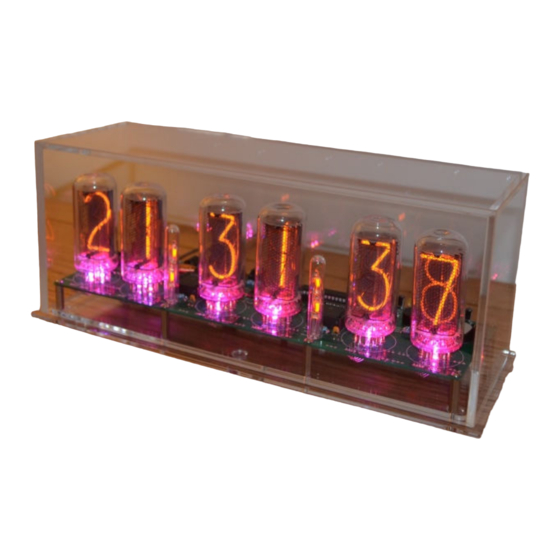
REVISION HISTORY Issue Date Reason for Issue Number 15 Feb 2015 Errors in Resistor values corrected Resistor networks not polarized 10 Feb 2015 New document Nixie Tube Clock ‘Spectrum 18’ - 2 - Issue 2 (15 February 2015) www.pvelectronics.co.uk... - Page 3 RODUCTION 1. INT Here are the key features of the SPECTRUM 18: Hours, Minutes and Seconds display on Six IN-18 Nixie Tubes • • 40mm (1.5”) Digit height • Noiseless, Direct Drive giving optimum digit clarity • Dedicated, plug-in High Voltage Module (Included) Uses a Quartz Crystal Oscillator as the timebase •...
- Page 4 This is not a finished product, and the person assembling the kit is responsible for ensuring that the finished product complies with any applicable local regulations governing electrical equipment, eg. UL, CE, VDE. Nixie Tube Clock ‘Spectrum 18’ - 4 - Issue 2 (15 February 2015) www.pvelectronics.co.uk...
-
Page 5: Tools And Equipment Required
The following type of adapter should be obtained and used with the kit: Output 12V DC regulated, minimum power output capability of 1A Output plug: 2.1mm pin, centre positive. A suitable adapter is shown below: Nixie Tube Clock ‘Spectrum 18’ - 5 - Issue 2 (15 February 2015) www.pvelectronics.co.uk... -
Page 6: List Of Components
Surface mount 3.5mm jack socket PIR and PIR2 Surface mount 3.5mm jack socket Piezo sounder FUSE 500mA fuse 1KΩ Potentiometer 32.768KHz watch crystal HV Module High Voltage Module in header Nixie Tube Clock ‘Spectrum 18’ - 6 - Issue 2 (15 February 2015) www.pvelectronics.co.uk... - Page 7 2.1mm PCB power socket Surface mount 3.5mm jack socket Piezo sounder 1A fuse 1KΩ Potentiometer 2 way header with jumper 6 way female header 0.1” 32.768KHz watch crystal Nixie Tube Clock ‘Spectrum 18’ - 7 - Issue 2 (15 February 2015) www.pvelectronics.co.uk...
- Page 8 PCB, so that the PCB can fit inside a case with the tubes protruding. Please follow carefully the instructions. Unless specified otherwise, please solder all components on the top of the PCB. Nixie Tube Clock ‘Spectrum 18’ - 8 - Issue 2 (15 February 2015) www.pvelectronics.co.uk...
- Page 9 For each socket holder, you need to push in 11 socket receptacles. Push them in from the ‘SOCKETS THIS SIDE’ side. Push them with the 2 open jaws going in first. Look at the photo below. Nixie Tube Clock ‘Spectrum 18’ - 9 - Issue 2 (15 February 2015)
- Page 10 Solder the 6 resistor networks on the bottom side of the PCB as shown below. These parts are not polarized, so the orientation does not matter. Nixie Tube Clock ‘Spectrum 18’ - 10 - Issue 2 (15 February 2015) www.pvelectronics.co.uk...
- Page 11 There is only one way the socket can be inserted, so it should be impossible to orient incorrectly. After soldering all 66 contacts, clip off the lower, very thin part of the connector. Nixie Tube Clock ‘Spectrum 18’ - 11 - Issue 2 (15 February 2015) www.pvelectronics.co.uk...
- Page 12 This must match the cross hatched side on the PCB Marking. Please note that J1 and L1 must be soldered on the bottom of the PCB is all cases. Nixie Tube Clock ‘Spectrum 18’ - 12 - Issue 2 (15 February 2015) www.pvelectronics.co.uk...
- Page 13 28 Way IC socket for IC2 R1 (6.8 KΩ) VR1 (1 KΩ Potentiometer) HV Module Start by soldering the 6 way male header to the HV Module. Nixie Tube Clock ‘Spectrum 18’ - 13 - Issue 2 (15 February 2015) www.pvelectronics.co.uk...
- Page 14 Here you can see how the 6 way female header is soldered on the bottom of the PCB: And now you can push the HV Module into place: Nixie Tube Clock ‘Spectrum 18’ - 14 - Issue 2 (15 February 2015)
- Page 15 PCB will sit neatly during the tube test. With great care, and looking carefully at tube alignment (tube faces forwards), insert six IN-18 Nixie Tubes into the sockets. Nixie Tube Clock ‘Spectrum 18’ - 15 - Issue 2 (15 February 2015)
- Page 16 Note: C6 and the 2 Way jumper need to be soldered on the bottom side of the PCB if you are mounting the clock in the Visio case. Nixie Tube Clock ‘Spectrum 18’ - 16 - Issue 2 (15 February 2015)
- Page 17 RGB lighting from the tube LEDs provides sufficient illumination of the colon neons. Start by bending the leads of each RGB LED as shown below, noting the orientation of the longest lead. Nixie Tube Clock ‘Spectrum 18’ - 17 - Issue 2 (15 February 2015) www.pvelectronics.co.uk...
- Page 18 If you follow the bending instructions above, then the longest lead should go into the hole marked with 2 small circles at each RGB LED location. Solder each LED and clip the leads short. Nixie Tube Clock ‘Spectrum 18’ - 18 - Issue 2 (15 February 2015)
- Page 19 500 (2”) long: Next, cut the clear heat shrink tubing into 8 lengths: 4 lengths of 20mm and 4 lengths of 45mm: Nixie Tube Clock ‘Spectrum 18’ - 19 - Issue 2 (15 February 2015)
- Page 20 Finally, solder the neons in place on the PCB, with the taller neons at the back. The glass cover tubes can be placed over later. Nixie Tube Clock ‘Spectrum 18’ - 20 - Issue 2 (15 February 2015)
- Page 21 This is only applicable if your PCB is dated 6 January 2015. Solder a wire link as shown below, between the middle pin of Q4 and pin 10 on IC2. Nixie Tube Clock ‘Spectrum 18’ - 21 - Issue 2 (15 February 2015) www.pvelectronics.co.uk...
- Page 22 It will show for several seconds and then move to parameter 1. In all correspondence on support issues, please quote the board type, revision date and software version. Nixie Tube Clock ‘Spectrum 18’ - 22 - Issue 2 (15 February 2015)
- Page 23 0 – No PIR installed (default) Period 1 – 15 seconds 2 – 30 seconds 3 – 1 minute 4 – 2 minutes 5 – 5 minutes 6 – 10 minutes Nixie Tube Clock ‘Spectrum 18’ - 23 - Issue 2 (15 February 2015) www.pvelectronics.co.uk...
- Page 24 6 – Fahrenheit display, every hour Thermometer offset 0 – 10 degrees Restore default settings 0 – Keep user settings 1 – Restore original default settings Nixie Tube Clock ‘Spectrum 18’ - 24 - Issue 2 (15 February 2015) www.pvelectronics.co.uk...
- Page 25 ‘SET’ as you power up from a cold start. A cold start is a startup with a fully discharged Supercapacitor, or with the Supercapacitor jumper removed. Nixie Tube Clock ‘Spectrum 18’ - 25 - Issue 2 (15 February 2015)
- Page 26 00 (off) or 01 (on). Set on / off status, then minutes followed by hours by using the ‘ALARM’ and ‘ADJ’ buttons. When set, the alarm LED will also light. Nixie Tube Clock ‘Spectrum 18’ - 26 - Issue 2 (15 February 2015)
- Page 27 5 full days (120 hours). Program this value into parameter Set parameter 21 to 0 to slow down the clock and to 1 to speed up the clock. Nixie Tube Clock ‘Spectrum 18’ - 27 - Issue 2 (15 February 2015)
- Page 28 • Once you are happy with the colour for that hour, press ‘DST’ to move to the next hour • Have fun playing with your favourite colours and intensities! • Colours are displayed live during RGB menu: Nixie Tube Clock ‘Spectrum 18’ - 28 - Issue 2 (15 February 2015) www.pvelectronics.co.uk...
- Page 29 • In the example below, between 19 and 20 hours, the LEDs will be blue with a hint of green ( 0 red, 2 green and 8 blue) Nixie Tube Clock ‘Spectrum 18’ - 29 - Issue 2 (15 February 2015)
- Page 30 Blue value has no effect. Note: The colours do not cycle live during Auto Colour Cycling setup. The cycling starts only during normal time and date display. Nixie Tube Clock ‘Spectrum 18’ - 30 - Issue 2 (15 February 2015)
- Page 31 Select blanking during time seek by setting parameter (25) to 1. Nixie Tube Clock ‘Spectrum 18’ - 31 - Issue 2 (15 February 2015)
- Page 32 3. The time signals are intended that a receiving clock may collect time data intermittently. The signal strength and fidelity is not like a 'TV Signal', where one can get a perfect signal any time at will. Nixie Tube Clock ‘Spectrum 18’ - 32 - Issue 2 (15 February 2015)
- Page 33 Metal objects cause reception problems too Place and design your case so the antenna is as far away from the PCB as possible. Nixie Tube Clock ‘Spectrum 18’ - 33 - Issue 2 (15 February 2015)
- Page 34 Connecting a GPS receiver The clock has been designed for, and tested with our Micro GPS Receiver (available separately from PV Electronics) Nixie Tube Clock ‘Spectrum 18’ - 34 - Issue 2 (15 February 2015) www.pvelectronics.co.uk...
- Page 35 Sync > 24 Seeking Aquiring Source 2 Hrs Sync < 24 RFT Frame Frame None DCF / MSF Slow Flash Intermittent Fast Flash Flash Slow Flash Nixie Tube Clock ‘Spectrum 18’ - 35 - Issue 2 (15 February 2015) www.pvelectronics.co.uk...
-
Page 36: Pir Motion Sensor
Therefore, it does not override Night Blanking and Master Blanking. The suggested initial PIR period is 10 minutes (Config 17 = 6). Nixie Tube Clock ‘Spectrum 18’ - 36 - Issue 2 (15 February 2015) - Page 37 O/C: Connection to an open collector output (transistor is MPSA42) GND: Main connection to clock GND. This is an advanced feature. If you require further information, please send us an email. Nixie Tube Clock ‘Spectrum 18’ - 37 - Issue 2 (15 February 2015) www.pvelectronics.co.uk...
- Page 38 Shorting the two ‘RGB’ pads will switch off the RGB LEDs. Shorting the two ‘TUBES’ pads will switch off the High Voltage, and therefore the tubes will extinguish. Nixie Tube Clock ‘Spectrum 18’ - 38 - Issue 2 (15 February 2015)
-
Page 39: Circuit Diagram
11. CIRCUIT DIAGRAM Nixie Tube Clock ‘Spectrum 18’ - 39 - Issue 2 (15 February 2015) www.pvelectronics.co.uk... - Page 40 Nixie Tube Clock ‘Spectrum 18’ - 40 - Issue 2 (15 February 2015) www.pvelectronics.co.uk...
- Page 41 Nixie Tube Clock ‘Spectrum 18’ - 41 - Issue 2 (15 February 2015) www.pvelectronics.co.uk...
Need help?
Do you have a question about the Spectrum 18 and is the answer not in the manual?
Questions and answers