Table of Contents
Advertisement
Advertisement
Table of Contents

Related Manuals for Monty e-bike E-132


Summary of Contents for Monty e-bike E-132
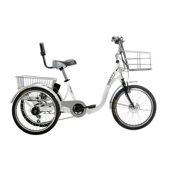
- Page 1 USER’S MANUAL ELECTRIC TRICYCLE E-132...
- Page 2 PRESENTATION WELCOME TO THE MONTY FAMILY We want to greet and give you our thanks for having chosen our Monty brand. This “Own manual” contains important and awful information to help you for a correct use of the new Monty electric Kit. It has been made in order that you can enjoy of the electric KIT with security and reliability, obtaining the maximum of its performance.
- Page 3 GENERAL RULES • Please read this Manual thoughtfully before using the Monty KIT for the first time. • Ensure that the bike Works correctly before riding. • Not to change the technical characteristics of the KIT or to add anything which could interfere with them.
-
Page 4: Table Of Contents
INDEX IDENTIFICATIÓN OF THE PARTS…..................6 UNDERSTANDING ICONS…....................6 ELECTRICAL PARTS ASSEMBLING........................1 1.1 WHEEL ASSEMBLING....................7 1.1.1 Front wheel removing……………..:..............7 1.1.2 Tyre setting……………….:.................7 1.1.3 Assembling KIT wheel to the fork…………............7 1.2 BRAKE ASSEMBLING / SHIFTING……..............8 1.2.1 Lever shifting …………………….................8 1.2.2 Brake levers & shifting grip…..…..……………............8 1.3 ELECTRIC INSTALLATION..................9 1.3.1 Cables fitting…………..................9 1.4 CONNECTIONS......................9... - Page 5 PRESSURE CHART…....................20 7.3 LUBRICATION AND CLEANING................21 7.4 BRAKES WORK AND PERFORMANCE…..………………........21 7.5 BRAKE CHECKING…..…..................22 7.5.1 RIM BRAKE SYSTEM………................23 7.5.2 VERIFICATION....................23 7.6 AJUSTEMENT.....................23 8 ELECTRONIC COMPONENTS..................25 8.1 CONTROLLER….......................25 8.2 ENGINE........................25 KIT CHARACTERISTICS……..................25 ELECTRIC SCHEME….....................26 SOLUTION CHART………....................27 WARANTEE........................29 FREQUENT QUESTIONS…....................29...
-
Page 6: Identificatión Of The Parts
IDENTIFICATION OF THE PARTS VERIFICATIÓN: Open the KIT box by the cap of the superior part and verify that all the mentioned parts are being included. 1. Lithium battery 5. Right brake lever 2. Left brake lever 6. Speed control and contact 3. -
Page 7: Electrical Parts
ELECTRICAL PARTS 1 ASSEMBLING The Kit assembling must be done in stable position and in horizontal way with some basic mechanic and electric knowledge. It is advisable to be assembled by an official mechanic. It is recommended to follow the bellow steps:: Wheel assembling, Brake / control assembling, Electric parts fitting, Connections 1.1 WHEEL ASSEMBLING 1.1.1 FRONT WHEEL REMOVING:... - Page 8 First loose the nuts of the brake cables in order to take them out through the tensors. (Figure 4). Remove the brake levers and the shifting control. (Figure 5). Loose the brake levers with an Allen of 5mm. Loose the shifting control with a star screwdriver. ...
-
Page 9: Connections
Fit the brake /speed control electric cables in a parallel position to the brake cables. Envelope the cables with a spiral band for a correct fixing.(Figure8). The cables must be set along the frame in a smooth way (Figure 9) to the rear battery bag where all the connections must be connected Figure 10). -
Page 10: User's Guide
There are two tubes getting out from the throttle composed by three wires / White, Black and Red). The three must be connected to the controller through a connecting link with three wires (Yellow, Black and White) The thin cable corresponds to the throttle, composed by three wires (White, Black and Red) and they must be connected to the controller by a connector with three wires ( Yellow, Black and White) respectively. -
Page 11: Kit Performance
Figure 14 2.2 KIT PERFORMANCE The electric bicycle or tricycle fitted with the KIT: MONTY E-132 has a simple performance. It is the same as riding a conventional bicycle but with the help of an engine, as an electric bicycle. -
Page 12: Battery And Charger
Figure 15 Figure 16 See: Battery and charger. 2º To initiate the first riding of the vehicle: One shall Poly press the speed grip (throttle) to go forwards and the engine is to work automatically. One can regulate the engine speed by the throttle, more you turn the grip, the quicker the engine is to go, till a maximum speed of 23 km/h. - Page 13 The KIT is provided with a Lithium battery of 36V-9Ah The lithium battery provided by the KIT 302 does mot need a precise maintenance but yes advisable stops to follow: It must be charged before any riding. Even stored, the battery must be checked ...
-
Page 14: Battery Fuse
1. Remove the charger from the battery bag to get the battery enough ventilation. Check the charge voltage to be the same than the fuse of the net system (220v). The charger specifications are impressed on them. 2. First connect the charger cable (B) to the battery connector (A), Figure (18). Make sure to be well fixed). -
Page 15: Verifications
If the KIT is not to be used for a long time, the battery should be let charged the 50 % of its capacity and to make a maintenance charge one time per month. Use always the charger provided with the KIT. The battery charge is to depend on the consume which had had. -
Page 16: Verification Points
• Correct tighten of the quick releases. Takes note as normal the following points mentioned below before using the KIT. 4.2 VERIFICATION POINTS: WHEELS The tires and the rims are important parts for the right performance of the KIT. 302. Check the correct pressure of the tires and the run out of them and the estate of the rims. -
Page 17: Advices
Keep a moderate distance with the other vehicles and other objects. Calculate the brake capacity with respect to the distance. Adjust the distance braking capacity. To stop the KIT, grip both levers at the same time. The excessive use of the front wheel can provoke a skid on the front wheel, even the rear wheel may lost contact with the ground. - Page 18 Do not use the speed grip constantly Keep the tires pressure to be right Verify the rakes not to touch the rims. Keep a media speed if it is possible. When the KIT had to be stopped, use the brakes in a carefully way, letting the KIT losing speed by itself.
-
Page 19: Ajustments
ATENTION: As any mechanical device, the KIT is to wear down along the time. The different materials and components used react differently to this daily decline. If the lasting of any item has been finished it can be broken, causing injuries to the user. The cracks, scratches or discoloration of the items can be a signal of intense use, therefore they should be changed. -
Page 20: Pressure Chart
on them. On changing the tires, make sure them to have the right size to the rim and the Vehicle type. CAUTION On replacing the tyre, make sure to have taken a tyre compatible with the rim and type for the KIT. The KITS tires have special characteristics different from standard ones. -
Page 21: Rim Brake System
Clean and lubricate the chain and sprockets once a month. Avoid excess grease falling on the rest of the KIT by placing a rag behind the chain. Once the chain has been lubricated, wipe off any excess grease with a rag. Do not use gasoline to clean the sprockets as if it is highly inflammable and can let a thin film of grease on evaporating. -
Page 22: Ajustement
Check the brake shoes state one time per month. The brake shoes may have groves on their surfaces, if any of them are less than 2mm deep, they will have to be changed and 1mm in the V-brakes system. In the case that the brake shoes had not grooves, they will have to be replaced when they were only 3mm left of the rubber block. -
Page 23: Electronic Components
HOW TO REMOVE THE WHEELS V-BRAKES type: The connection tube should be disconnected. Press with a hand the brake shoes against the rim and with the other hand, pull the tube backwards from the connecting point and get up the tube. Once disconnected, on getting out the brakes shoes, the tube is to get out as well. -
Page 24: Engine
KIT CHARACTERISTICS Model KIT TRICYCLE Battery Lithium Voltage 36 V. Capacity 9 Ah. Range (years) Nº Charges 300 Aprox. Charging time 4-6 hours Leed charger 220 V Weigh 3 Kg Engine 250W Type Brushless Fork width 100 mm Cable side Left Importance of the use of original parts It is extremely important to use always original parts when replacing the KIT components. -
Page 26: Solution Chart
SOLUTIONS CHART: INCIDENCE POSSIBLE CAUSE SOLUTION After setting the battery 1. The battery may be 1. Charge the battery. to be charged, there is discharged on the whole. 2. Change the fuse. not indication of being 2. The fuse is out or order 3. -
Page 27: Warantee
WARANTEE A warrantee is being established through the vendor in accordance with the law /2003, dated July 10, on the consumer sales warranties, according to the Directive normative 1999/44CE. Additional conditions: The warrantee does not cover the KIT parts subjected to normal run out use such as tires, chain, brakes, cables etc. -
Page 28: Frequent Questions
FRECUENT QUESTIONS Can one use the KIT without the battery? Yes, no problem, however, if you remove the battery, the lights are not to work. Where is the identification frame number? It is engraved underneath of the headset tube. It begins with the model number, for example 301xxx In what direction the pedals must be thread? (See the required section) - To assemble them: They must be fixed on the same direction that the wheels turn when...
Need help?
Do you have a question about the E-132 and is the answer not in the manual?
Questions and answers