Table of Contents
Advertisement
Quick Links
Advertisement
Table of Contents

Related Manuals for Si-tex SVS-760F


Summary of Contents for Si-tex SVS-760F
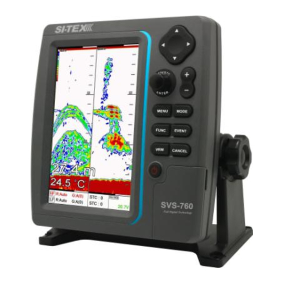
- Page 1 SVS-760F FISHFINDER OPERATIONS MANUAL - 1 -...
- Page 2 WARNING Always follow this safety instruction to prevent death or injury. Follow this safety instruction to avoid possible injury or damage to your property. CAUTION Symbol “△” is a CAUTION or WARNING label indicating the safety instruction. WARNING This symbol is an Electrical Shock WARNING label. Symbol is an instruction that you must not violate.
- Page 3 WARNING <For System Operators> Always follow this instruction to prevent death or personal injury. If smoke or a small of burning occurs, a fire or Turn power an electrical short circuit may result. Turn the power switch OFF and shut down the power During supply immediately.
-
Page 4: Installation Cautions
Installation Cautions <For service Personnel> Follow installation instructions to avoid personal injury and system malfunction. Installation in Mount your SVS-760 on a rigid frame or base to prevent rigid location. your unit from working loose. Use correct Use the installation materials provided in the standard Installation accessory pack only. -
Page 5: Maintenance Cautions
Maintenance Cautions<For Maintenance Personnel> Use the following safety precaution internal inspection. High voltage may be retained in the capacitors if the Discharge high-tension circuit several minutes after you have capacitors. turned the power switch off. To prevent an electrical injury due to erroneous power switching, make sure that the main power supply and Check that power the system power switch are both in the off position. -
Page 6: Operation Notes
Operation Notes <For operators> Observe the following operation notes, otherwise the system failure or deterioration can result. And periodical inspection and maintenance are required for keeping the system in an optimum condition. The waypoint and other registered data may become Backup important unreadable by unexpected failure. - Page 7 SVS-760 Fishfinder System CAUTION The SVS-760 Color LCD Fishfider Systems employs the latest in proven technology to provide accurate fish & bottom information. The Plotter functions of SVS-760 are totally dependent upon the capability of the navigation source to provide accurate position information. This device is only an aid to navigation.
- Page 8 ▶ A large 7” Direct Sunlight Viewable High Definition LCD Display, in a vertical format to provide maximum sonar resolution! 480 x 800 pixels. ▶ Fishfinder offer’s Superior fish detection and bottom discrimination using the new SI-TEX All Digital Sounder System.
- Page 9 Features of the SVS-760 ▶ 10 Page Screen Capture Memory allows you to take Snap Shots of the Fish Finder Screen and save them to memory. ▶ 10 Event point memory allows you to instantly save a Fishing location and compute your course steering info back to the spot.
- Page 10 Fishfinder System Introduction The SVS-760 is a premium multifunction command and control center. SVS-760 front panel keyboard and its wide screen with wide viewing area make placement easy. Although SVS-760 offers many advanced features, operation is simplified through the use of popup menus similar to those found on personal computers.
- Page 11 Fishfinder system Keypad Description With MENU: Choosing the menu [Cursor Without MENU: Choosing frequency Key] (50/200KHz) [GAIN] Button: Enter when menu table on the screen & Rotary: Adjustment of gain level with turning. [ENTER] Setting up the depth range, when depth range [+] &[-] sets “manual range”.
- Page 12 Fishfinder system How to use [Power/Brightness] ▶ Press [PWR/BRT] 1.Use PWR: To turn off the power, keep pressing the [BRT/PWR] until the end of counting. 2.Use BRT: Press [BRT/PWR] shortly and the brightness can be controlled. Use the arrow keys [←][→]of the cursor to control the brightness and the contrast.
- Page 13 Fishfinder system Plastic <Front> 7 inch Color LCD Keypad Knob Mounting Bracket <Rear> Connector - 13 -...
- Page 14 Fishfinder system SPEC of the connectors (Plastic) - 14 -...
- Page 15 - 15 -...
- Page 16 SVS-760 Introduction Fishfinder - How it works- The SVS-760 echo sounder consists of a transceiver display unit and a dual frequency transducer. An electronic signal pulse is generated in the transmitter section of the display unit. When coupled to the transducer, this signal is converted into an ultrasonic signal and is transmitted toward the bottom. The signal travels through the water until it strikes an object or the bottom.
- Page 17 Installation of the SVS-760 A careful installation will assure maximum performance from your new SVS-760. Display Unit Location Select a location for your Display unit that provides easy viewing from all likely operator’s positions. The display unit is designed to be mounted on either a console or from an overhead surface. The Display unit is also designed for flush mounting using six threaded holes on the rear panel.
-
Page 18: Installation
Installation Drill a 1/4 in. diameter hole at each marked location. Mount the Display unit bracket using bolts through the mounting surface. Place large flat washers on the opposite side of the mounting surface from the bracket and then install lock washers and nuts. Tighten securely. Install the display unit into the mounting bracket. - Page 19 SVS-760 Transducer Options Model # Beam Angles Type Hole Size 45º @ 50kHz Plastic transom mount w/ 250/50/200ST-CX 11º @ 200kHz depth, spd, temp. 45º @ 50kHz Bronze thru hull depth & 1700/50/200T-CX 7/8" 11º @ 200kHz temp. 45º @ 50kHz Bronze thru hull depth, 500/50/200ST-CX 2"...
- Page 20 Secure the cable in place using Nylon Wire Ties. Coil the extra cable and tie it out of the way. 4th) If transducer cable is not long enough, 15 & 30 foot extension cables are available from SI-TEX When you attach the extension cable, be sure that the connections are tight and watertight. Use Dow Corning DC-4 or an equivalent sealing compound to protect the connector assemblies.
- Page 21 Installation Installing the Power Cable ) The 6-foot power cable supplied with the display unit should reach the source of DC power. Connect the power leads directly to the main battery isolation switch or breaker, or route the power leads to the DC power distribution panel. At the power source, connect the red wire to the positive terminal (+), and the black wire to the negative terminal (-).
- Page 22 Installation Installing a Thru-Hull Transducer Follow these instructions if you are installing the thru-hull transducer. ) Once you have decided where to install the transducer, drill the hole for the part. Begin by drilling a small pilot hole (1/8" or 3mm) from the inside of the hull. (This small hole can be filled easily if the mounting location is not suitable.) Before you drill the hole, be sure you will be able to reach the large nut on the top of the transducer, once it has been mounted.
- Page 23 Installation Installing a Thru-Hull Transducer ) Go to the inside of the hull and slide the hex nut over the end of the cable. Fit the hex nut over the end of the transducer and tighten it. (On a vessel with a wooden hull, do not tighten the nut completely right away.
- Page 24 Installation Positioning the Transom-Mount Transducer Follow these instruction if you are installing the transom-mount transducer. Begin by finding the best location for the mounting bracket. Here are the rules: If your boat has one propeller (outboard or inboard-outboard), mount the transducer about 18"(455mm) to the side of the centerline of the boat.
- Page 25 Installation Mounting the Transom-Mount Transducer Follow these instructions if you are installing the transom-mount transducer. ). On a boat with a fiberglass hull, the leading edge of the transducer should extend 1/8""(3.2mm) to 1/4""(6mm) below the bottom edge of the hull. See picture 1-3. On an aluminum hull, the transducer should extend a bit more - 1/4"(6mm) to 3/8"(9mm).
- Page 26 Installation ) Tilt the transducer in the brackets until it is positioned as illustrated in Picture 1-3 ) Once the bracket is in the correct position, you can tighten the screws. - 26 -...
- Page 27 Installation NMEA-0183 Interfacing to a GPS The power cable used on the SVS-760 provides for both DC power connection and for the Input output connections for NMEA-0183 devices such as a GPS Navigators or Chart plotters. NMEA-0183 Description $GPDBT Depth below transducer $GPDPT Depth $GPMTW...
- Page 28 Operation of the SI-TEX SVS-760 Fishfinder Modes The SVS-760 Fishfinder modes are selectable for single frequency or dual frequency, and split screen functions, for example bottom zoom or bottom lock. FISH FINDER MODES Normal 200khz Bottom Zoom 200khz Bottom Lock...
-
Page 29: Operation
Operation 2. Bottom Zoom (200KHz or 50KHz) Bottom Zoom magnifies the sounder display from the sea bottom toward the surface for a short distance. The sea bottom contour is displayed and additional contour lines are added at intervals above the sea bottom to aid in determining distances of echoes near the bottom. Use the Sounder Menu to set the magnified Bottom Range from 2.5 to 20m (10 to 60ft.). - Page 30 Operation Fishfinder Low Frequency High Frequency Depth bar Red color : It is selected to Data bar setup Frequency - 30 -...
- Page 31 Operation FF + Highway The highway display provides a 3D view of own ship’s progress toward destination (waypoint). Destination waypoint name Bearing from own ship to destination Course Over waypoint Ground Destination Range from own waypoint ship to destination Speed Over waypoint Ground XTE Alarm Radius...
- Page 32 Operation FF + Steering The steering display provides steering information such as ship’s speed, course, range, bearing, TTG. Bearing from own ship to destination waypoint Course Over Ground Bearing from Rang own ship to from destination ship to destinati Cross-Track-Error Destination waypoint Time-To-Go to destination name...
-
Page 33: Select Page
Operation Select Page Select [Page] menu and then go to “Pages” screen Selectable Pages by red box and then press [ENTER] key. red box - 33 -... - Page 34 Operation Customize of screen Press [FUNC] key for 3 seconds on the Pages which selected red box.(*Refer Fig. 1.1.1 as below) Select the layout of the formation of screen.(*Refer Fig. 1.1.2 as below) Select displays .(*Refer Fig. 1.1.3 & 1.1.4 as below) <Fig.
- Page 35 Operation Customize of data bar ▶ [MENU] -> Setup -> Customizing -> Data bar edit Select the section to edit by red box. .(*Refer Fig. 1.2.1 as below) Press [ENTER] key and select the data as a user want.(*Refer Fig. 1.2.2 as below) Finish the formation of data bar, press [CANCEL] key to complete.
- Page 36 Operation Navigation data edit ▶ [MENU]-> Setup->Customizing->Navigation data edit Select the section to edit .(*Refer Fig. 1.3.1 as below) Press [ENTER] key and select the data as a user want. .(*Refer Fig. 1.3.2 as below) Finish the formation of data bar, press [CANCEL] key to complete (* If no navigation data on present activated display, it is not available to edit) <Fig.
-
Page 37: White Line
Operation Menu The menu and explanation of operation are displayed. ▶ Press [MENU] 1. Range JFC-7050 selects the best condition for measuring the depth automatically in the environment of the sea. (☞ The default setting is Auto.) 2. Shift \A user selects this function to see more detailed bottom of the sea. When you turn up the shift, the range of Sounder shall go up from the shift range. -
Page 38: Frequency Display
Operation 3.5.Depth 3.5.1. Display On/Off the depth range on the screen. (☞ The default setting is ON.) 3.5.2. Depth Font Select the depth range font size on the screen. (☞ The default setting is Normal.) 3.6.TEMP 3.6.1. Display On/Off the temperature on the screen. (☞... -
Page 39: Noise Rejection
Operation 3.9.1. Symbol Fish symbol with sizes and levels show for targets. (*Fish symbol is only for reference. This could be different from the real.) (☞ The default setting is Off.) 3.9.2. Size Display the size of fish on the window (*Fish size is only for reference. -
Page 40: Output Power
Operation 6. Pulse Select the pulse of the output from the transducer. Levels are among Low, Medium and High, which depends upon the depth. Low is proper to research precise a fish school but it is not suitable to measure a deep depth. High is opposite from Low. (☞... - Page 41 Operation 8.2.2. High Range It alarms when the set high temperature is out of the range. (☞ The default setting is 0.) 8.2.3. Low alarm It alarms when the set low temperature is out of the range. (☞ The default setting is OFF.) 8.2.4.
- Page 42 Operation 9. Setup 9.1. System It contains ID and the program version, and it has important information for maintenance and upgrade. 9.2. Unit 9.2.1. Distance/Speed Select desired unit of measure for distance and speed. Choose from: nautical mile/knots (nm/kt), kilometer/kilometers per hour(km/kmh), yard/knot(yd/kt). cf) 1nm = 1.852km, 1kt /h= 1.852km/h, less than 1nm display in yard and over 1nm display in mile (☞...
-
Page 43: Speed Source
Operation 9.4. Input/Output 9.4.1. Output Sentences The JFC-7050 allows customizing the NMEA.0183 sentence. NMEA Description Default $GPDBT Depth below transducer $GPDPT Depth $GPMTW Water temperature $GPTLL Target latitude and longitude $GPVHW Water speed and heading $GPGGA Global positioning system fix data $GPVTG Course over ground and ground speed $GPRMC... - Page 44 Operation 9.2.5. Water Temp The error of water temp value can be corrected. (setting:-10.0~10.0℃,-10~10°F) (☞The default setting is 0.) 9.2.6. Draft set The tolerance of depth can be corrected. Set the depth from the sea level to the set depth of your transceiver/receiver.
- Page 45 Operation 9.10.1.3. Edit It customizes the data bar information. 9.10.1.4 Mode It is available to set up the data bar. - Customizing : It is selectable and modifiable the data bar by user. - Fix mode : It is fixed data bar by default. It is not available selectable and modifiable the data bar by user.
-
Page 46: Key Setup
Operation 10. Others 10.1. Key Setup It is available to set up [FUNK] key and [EVENT] key on the JFC.7050. 10.1.1. [FUNC] key: Set the function frequently used for your convenience. (☞ The default setting is Page.) [FUNC]KEY SETUP 1.Page 2.Image Speed 3.Color Rejection 4.Noise Rejection... -
Page 47: Recording List
Operation 10.2.2.2. Arrival Radius: It is to adjust the range of arrival from your waypoint. If you have a route, it changes to the next waypoint automatically. (☞ The default setting is 0.05nm.) 10.2.2.3. XTE Alarm: If you are out of the course, it gives you a notice with alarm. (☞... - Page 48 Operation 10.6. Capture List Available to display and delete the capture file 10.7. Page Select the configuration & modification you wish. 10.8. Active Select the activated section. - 48 -...
- Page 49 Operation ▶ Press [VRM] The VRM (movable marker) shown by the green line can be moved up and down. It is convenient to measure the depth by aligning with the target such as school of fish. * Caution: When several seconds pass after finishing the VRM operation, the numerical of marker depth becomes normal display.
- Page 50 - 50 -...
- Page 51 - 51 -...
- Page 52 - 52 -...
- Page 53 - 53 -...
- Page 54 - 54 -...
-
Page 55: Certificate Of Limited Warranty
Defects will be corrected during normal working hours by an authorized SI-TEX Marine Electronics Inc. dealer, service center, or at the SI-TEX office in Riverhead, NY. There will be no charge for labor for a period of one year from the date of purchase, except as provided below under Limited Warranty Exceptions. - Page 56 VHF radio are items excluded from the two-year warranty and are covered by warranty for a period of one year for both parts and labor. SI-TEX Marine Electronics Inc. will not, at any time, assume any costs or labor charges for checkout or external line fuse replacement or problems not found to be at fault in equipment itself.
- Page 57 If you encounter problems during the installation or operation of this product, or cannot find the information you need, please contact SI-TEX Customer Service. The contact numbers and e-mail address for SI-TEX Customer Service are: SI-TEX Main Office…….………..+1-631-996-2690 SI-TEX Fax..………………….…..+1-631-996-2693 SI-TEX Service E-mail address: service@si-tex.com...
Need help?
Do you have a question about the SVS-760F and is the answer not in the manual?
Questions and answers